Up/Down Tron
spinner Up/Down Tron
spinner
One of my favorite games in the 80s was Discs of
Tron. It was an immersive game (for its day) being the only stand-up enclosed
cabinet, with speakers in front and behind, black-lit neon graphics, and background
artwork seemingly suspended behind the action.
Through Mame, I've been able to recapture some of the excitement of my teen years, but
something seemed to be missing. Then I remembered, due to a recent post about a DOT
control panel on ebay, that the original spinner could be pushed-in and pulled-out to move
the line of fire to hit Sark on the raised platforms.
I was in the middle of re-mounting my Oscar model 1, so, always the tinkerer, I determined
myself to add the additional functionality. 30 minutes later I had this:
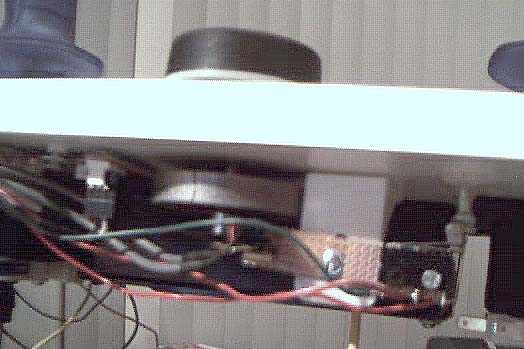
Okay, I know, my digital cam is one of those free things
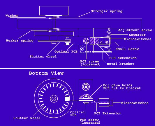
you get with DSL service--IT SUCKS.  So to make things clearer, I've blueprinted it for ya. So to make things clearer, I've blueprinted it for ya.

This was done with a model 1 plateless spinner, but should
work with other models as well. The design is very simple and uses maybe $2-$3 of
parts (a small circuit board and 2 roller actuator microswitches from Radio Shack).
Instead of some complex method of mounting the whole works on a moving platform, you
just use the existing optical circuit board as a lever (with some extension) and mount two
microswitches on the other end. The shutter wheel actually pushes the PCB
"lever" up and down, while staying aligned with the optics. This may seem
like a bad idea, but trust me, the microswitches take only a light touch and friction is
minimal. The shutter makes absolutley NO contact with the optics, just lightly
touches the groove in the PCB.
First, you remove any spacers from the spinner shaft, and replace them with springs.
I recommend using one spring above the control panel, and one below to help gravity
to quickly re-center it. I used about half of a spring from a Happ horizontal
pushbutton (the whole spring won't allow much compression, so you may have to cut it.)
The lower spring is weaker, it's from the buttons of a KYE Kidsball. Your
milage may vary, but the idea is just to get the spinner to center itself so there's the
same amount of space above and below the CP or mounting plate. I also put a washer
above the cut end of the top spring, to keep it from catching on the underside of the
knob.
Once it's mounted and centered, align the optic PCB with the shutter wheel as usual, and
tighten the screw that holds it to the L-bracket. Then, apply a gob of hot glue to
hold the nut (on the other side of the bracket) in place. Once the glue cools,
carefully loosen the PCB screw just enough so that the PCB pivots freely up and down.
Next, you extend the PCB. I used a piece of a small PCB that I cut to the same width
as the existing one by running a hobby knife across a row of holes and breaking it off.
This was hot glued to the existing PCB near the PCB screw. Drill 2 holes in
the PCB extension and with 2 small screws, mount the microswitches on opposite sides of it
as shown. Wire the switches using the normally open contacts, to the interface of
your choice. (I used player 1 buttons 7 & 8 on my IPAC.) Don't forget to
connect the grounds.
Lastly, you install the adjustment screw in the bottom of your control panel (Flat head
woodscrews work best), and a metal bracket connected to the bottom of your original PCB
bracket. The adjustment screw should line up above the end of the upward-facing
microswitch actuator, and the bracket should be under the downward-facing actuator.
Now, when you pull the knob up, the bottom switch hits the bracket and sends an
input to the computer. When you push down, the top switch hits the adjustment screw,
and sends a different input to the computer. Simple, huh?
I know this is about as clear as mud, but trust me, IT WORKS!!! Go now, and have
fun. 
|
| The
information on this site is for the purposes of education and
entertainment only. The owner of this site makes no warantees as to
the accuracy of the information, and takes no responsibility for any
damage or injury sustained due to the use of information herein. The
design of the Pac-Mamea cabinet and all photos, computer renderings,
drawings, schematics, and printed information relating to such are
Copyright © 2005 Robert Meyers. No ownership of other
copyrighted material found on this site is implied. |