.: Enhance your HotRod™

Adding a plateless OSCAR Model 1, a Joystick Restrictor kit, and additional buttons to a HotRod SE.

click on a picture for an enlarged view


drilling template
drilling template

The joystick shaft and the original carriage bolts that secure the joystick base to the control panel were removed.  A blank Joystick Restrictor mounting plate was then bolted to the top of the control panel and the joystick base on the underside with the screws supplied with the Joystick Restrictor kit.  This ensures the joystick is properly centered.  The holes for the Restrictor Plates were then drilled with a 3/16" & 1/4" bit, as required by the Mounting Plate hole sizes.

 
new button holes
new button holes
new button holes

Next, new pushbutton holes were drilled for extra buttons that will be mapped to "Esc" and "Tab" through the HotRod keyboard encoder.  The HotRod encoder is pre-programmed for these key inputs even though they are not used in the HotRod SE's standard configuration.

 
spinner location


spinner bearing


spinner installed


spinner installed


notch for spinner cable

The hole for the spinner bearing was located such that the knob would not interfere with Player 2's controls on the top, and also to clear the internal components, wiring, and physical space limitations.  In the pictures, you can see where the HotRod's internal braces were traced onto the underside of the control panel to prevent the spinner from being located where it would interfere with these blocks.  A small groove was cut at the bottom of the back panel for the spinner's cable to connect to the PC.  A knot was looped in the cable so if the wire were pulled, it wouldn't damage the spinner's internal PCB.

 
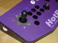
top view - no restrictors


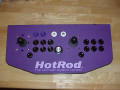
Player 1 side w/o restrictors


rear view - spinner cable


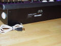
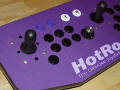
top view - restrictors installed


Player 1 side w/ restrictors
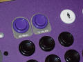
new button labels added
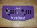
The joystick screws supplied with the Joystick Restrictor kit, which were installed in the first step, have now been removed and replaced with the original carriage bolts one at a time, thus keeping the joystick base properly centered.

Black hole plugs are inserted in the Restrictor Plate holes for a finished look when the restrictors are not installed.

The pinned connection for the Restrictor Plates works extremely well when the holes are drilled exactly perpendicular to the control panel and using the Mounting Plate as a guide.  This contradicts earlier information and comments made regarding the use of the Restrictor Plates without a Mounting Plate, as well as the  use of a pinned connection.  However, a lot more care was taken with the modification of this HotRod than during the prototyping/testing phase of the Joystick Restrictors, and it has shown that this style of installation is not only possible, but also gives excellent results when properly planned!


email:  Email for information


** Special thanks to Steve Marra for the opportunity to customize his HotRod SE! **


NOTE:  Performing these modifications may void any warrantee you may have on your HotRod (tm) joystick, per the warrantee and legal information as stated on HanaHo Games, Inc. website - link.

Copyright © 2002 Oscar Controls. All Rights Reserved.
http://mirrors.arcadecontrols.com/OscarControls

Oscar Controls is not affiliated with any company mentioned herein unless explicitly stated otherwise.


.: Home


Oscar Controls
general information :: Email for information
order/sales information :: Email Sales