Mini Test Bench RGB Monitor
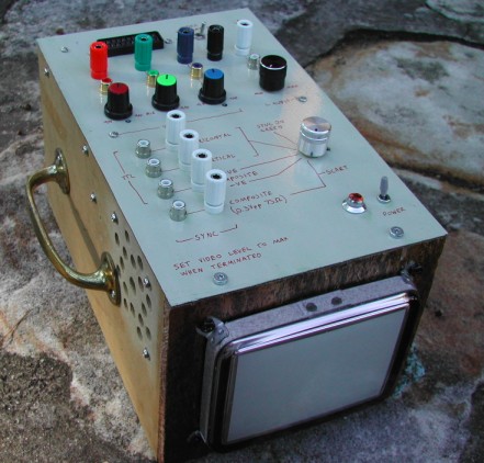
It's a 5" analog RGB monitor. Small enough to fit on a workbench without getting in the way.
Timeline Inc has a variety of surplus monitors for sale, one of which is the Samtron 5" Color Monitor. Unfortunately it's a digital CGA monitor that only accepts separate Horizontal/Vertical sync signals.
I've designed a couple of input stages that will transform them into super-monitors...or at least make them a bit more useful. There's two designs - they differ in the way the video is coupled to the input. The first circuit employs direct coupling. It requires the input video to have a DC component (typically arcade boards and computers output video of this type). The second circuit employs capacitive coupling and doesn't care whether the video has a DC component or not.
Direct Coupled Video Input Stage
(for arcade boards (JAMMA) + computers, digital RGB, etc)
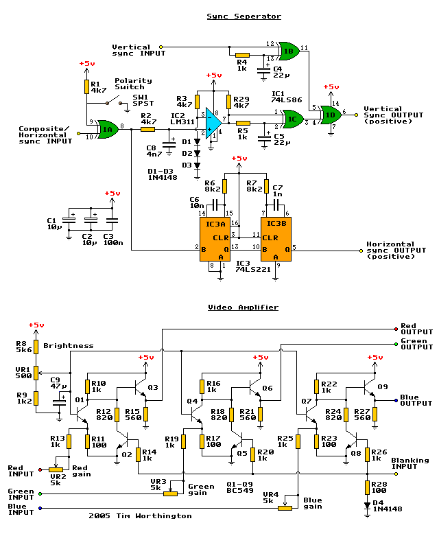
This circuit accepts composite sync or separate horizontal/vertical syncs. Polarity of the horiz or composite sync signal is set with SW1. The vertical input will adjust automatically to suit polarity.
Video input amplitude can range from 1.5Vpp to 5Vpp set by gain controls. Gain setting can be a bit fiddley due to the high gain of the first stage but it seems to work well otherwise.
Notes: BC548s should be ok instead of BC549s and C1/C2 can be electrolytic but tantalum is better. The parts used are all dirt common and cheap so there shouldn't be any sourcing problems.
This circuit runs at 5V and draws 34mA quiescent, and probably a bit more when actually doing something.
PCB Layout - Print at 600dpi
PCB Component overlay/wiring diagram
PCB Layout in Protel Autotrax format
Picture of prototype
Capacitively Coupled Video Input Stage
(for game consoles, SCART RGB, pretty much anything RGB)
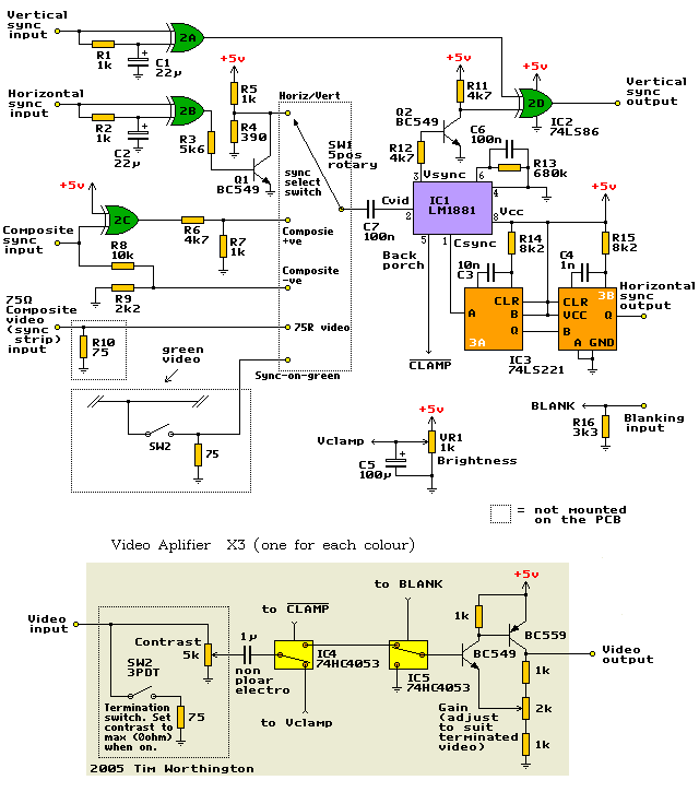
This input stage features DC clamping and 75 ohm termination. As well as the choice to sync to: horizontal/vertical, composite, 75R 0.3v composite, sync-on-green. It's more flexible than the previous one but it's also more complex and (due to the inclusion of the LM1881 IC) more expensive to build.
The 2k gain control trimpots should be adjusted to suit a 75 ohm 0.7Vpp video source. The video level is set by the contrast controls. Input amplitude can range from 0.5Vpp to 5Vpp.
Equivalents: a pair of plain old 4053s will work in place of IC4/5, an EL1881 will work as IC1 and I'm pretty confident that the BC549/559 can be replaced with any popular small-signal transistor (such as 2N3904/3906) without adverse affects (haven't tried it though).
This circuit runs at 5V and draws 30mA quiescent, 35mA max (measured).
PCB Layout - Print at 600dpi
PCB Component overlay/wiring diagram
PCB Layout in Protel Autotrax format
Picture of prototype - erm...just ignore the missing IC and the
"afterthought" coupling caps
Construction
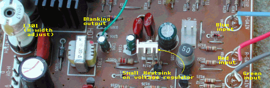
Modifications to the monitor board
Remove the red, blue and green gain pots, the video signal goes in where the wiper (middle
leg) went). It might be a good idea to add a small a heatsink to IC104, the 5 volt
regulator. Remove Q306, blanking output comes from the point where the base of this
transistor went. This is only horizontal blanking but it's better than nothing. I can't
thing of a easy way to get a V-blank signal from this monitor.
and here some Notes on the Construction of My Monitor
For my input stage I used the capacitively coupled design. There's also a small 1W audio amp in there. I desolderd an audio amp IC from a PC soundcard then built the circuit from an app note on a bit of proto-board. The amp lives in a little shielded box made from cardboard and foil - this keeps the hum to a minimum.
Originally I had planned to build the power supply into the box but the magnetic field surrounding the line transformer interfered with the CRT. Now I just use and external 12V power supply. The original filter/regulator is still in the box but it's not used.
The metal lid is was cut from the top of an old PC tower case. I labeled the surface with a fine tipped permanent marker then varnished it to stop the markings from coming off.
If the monitor is moved around a bit or placed near magnetic tools then the CRT's shadow mask can become magnetised. This causes colour purity and convergence problems and while not all that noticeable on a small monitor can get annoying. In mains powered monitors the solution is to degauss the monitor every time the monitor is started. This involves applying (current limited) AC line voltage to a coil that sits around the back of the CRT for a brief period of time.
To degauss (demagnetise) my monitor's CRT I've wired a TV posistor in series with the degauss coil then to a figure eight power socket mounted on the rear. When I want to degauss it I plug in a standard figure eight power lead and switch on the power point. After half of a second of pretty colours on the screen it's degaussed.
Resources
* Timeline Inc - the source of the 5"
samtron monitor
* Converting the Samtron 5" CGA monitor to
JAMMA - Similar idea to mine, though finding an EL4583C in Australia is difficult.
* Service manual
for an Imperial arcade monitor - The direct coupled design was based of the input
circuit of this monitor. PDF, 1.4MB
Page created 16/4/05
![]()