Fun with 555.
small projects and other misc stuff...
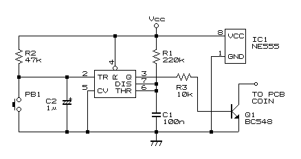
Replace a coin mechanism with a pushbutton.
Closes Q1 for ~24mS when PB1 is depressed.
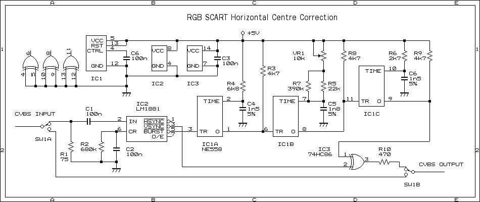
Adjust the centre position on any RGB SCART TV input without pissing about in the service mode.
TV Test Pattern Generator
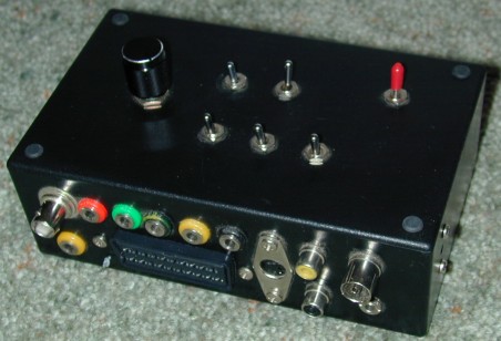
It's useful for making adjustments to TVs and as a video source. Patterns are colour bars, cross hatch, dots and full screen raster. It outputs RF (channel 3), composite video and RGB (from the SCART and banana sockets), there's also a 1khz audio tone output. The switches on the top control the pattern, colour, audio, red, green, blue and power.
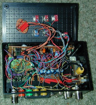 All the little boards are held in place with Blu-Tack :). Here's what they
all do....
All the little boards are held in place with Blu-Tack :). Here's what they
all do....
First is the Microcontroller board (vert. left) this is where all the brains lives. the uC is a PIC16F84. I didn't write the code for it, just took the code from here and programed the uC with it. The RGB video goes through a few resistors to the Video Encoder board (greenish) which is a chunk of circuit board cut out of an old sega master system II game system. This is the bit that takes RGB and spits out composite video. It needs some other bits to run properly which are located on the other bits board (to right). This includes a 4.43MHz oscilator for the video encoder chip, a bunch of coupling caps and a voltage regulator. The metal box to the right is the RF Modulator also from the sega game system. Last, and probably least is the Audio Oscilator board (vert. right) based on a 555 timer.
Last updated 22/9/09