How to use a SCART TV as a Monitor for MAME
As the title suggests this is guide to connecting a PC to a TV via it's SCART (aka Peritel or Euroconnector) socket. Specifically, for use with the arcade game emulator AdvanceMame (a port of MAME specially for arcade monitors and TVs) though the info is just as valid for other applications.
There's not a lot of difference between a TV and an arcade monitor. A TV can be thought of as an arcade monitor + a TV tuner + an audio amplifier in a plastic box. To use a TV as an arcade monitor the TV must provide inputs for RGB video which comes out of arcade boards, computers, etc. Here's where the SCART input comes in, not only does it accept RGB video (0.7Vp-p @ 75ohms, same as a computer monitor) it also has a couple of handy control lines. There are TVs with RGB inputs that use something other than a SCART input but they are quite rare. SCART sockets are often found on TVs found in Europe/Australia. Sometimes a TV can have more than one SCART input, usually one socket accepts Luma/Chroma (S-Video) and the other RGB video.
Note: Much of this information is not applicable to arcade monitors. Please see the Arcade Monitor Interface Circuits page if that's what you're after.
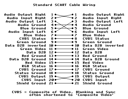
More info + pinouts for the SCART connector
The Circuit/Cable...
Fixing the Sync
In order for the TV to accept video from the PC we must first:
1. Run special software (AdvanceMame in this case) the PC to reduce horizontal scan rate
from ~31khz to ~15khz
2. Combine horizontal and vertical sync signals to make 'composite video sync' (0.3v/75
ohms).
3. Take the CVBS status line high (10-12v) to enable input from pin 20 (composite video)
4. Take the RGB status line high (1-3v) to enable input from pins 7, 11 and 15 (RGB)
Some (expensive) TVs can automatically switch the status lines themselves when a signal is present but most don't. Also some TVs will switch CVBS on with only 5v on the CVBS Status line but the majority need the full 12 volts.
Here are two circuits for combining the sync signals...
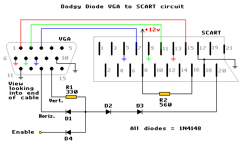
Horizontal and vertical sync signals must be negative for the circuit to function (this is the default for AdvanceMame).
This circuit ANDs the two sync signals together using diode logic. The H and V sync signals from the video card need to be able to source/sink a reasonable ammount of current for this circuit to operate properly. This isn't a problem for every modern video card I've come across but may be for older (ISA) cards. Pin 11 of the VGA connector is connected to ground to tell the computer that a colour 'monitor' is connected (sometimes this pin is already wired to ground inside the connector).
The Enable input is to facilitate shutting down (kill) the sync during boot (more info down the page). If this feature isn't required then D4 can be omitted.
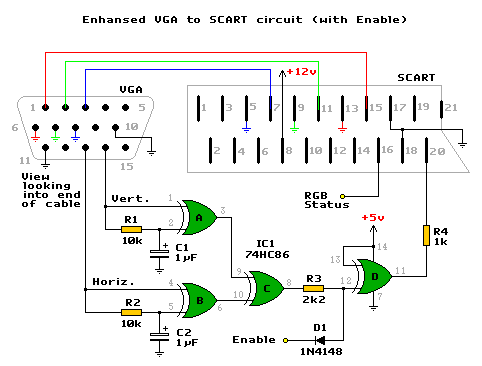
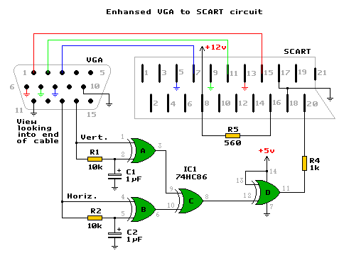
This circuit will adjust to any sync polarity making it much more versatile than the
'Dodgy Diode' circuit. It also XORs the two sync signals instead of just ANDing them. If a
TV has problems syncing to the output of the simple circuit this might resolve them.
C1, R1, IC1A and C2, R2, IC1B are there to adjust the polarity to to the input of IC1C. IC1C is to XOR the two sync signals together to make composite sync. IC1D inverts the composite sync which is output through a resistor (to drop the voltage to 0.3Vp-p) into the composite sync input.
Here is a version without an enable input.
During boot the video signals from the PC will be at a frequency to high for the TV to handle. Feeding the TV these signals will cause it to loose sync and produce an unstable/rolling/duplicated image. Aside from being annoying it can, in some cases, cause damage to the TV. To prevent the wrong signals reaching the TV, an Enable input has been added to both VGA > SCART circuits. This allows the sync to be disabled during boot (or any other time the H. frequency is too high). There's also a RGB Status input to the SCART socket which will blank the screen when off. This is usually turned off with the Enable line to stop out of sync video appearing on the screen.
| Input | Off | On | Impedance |
| RGB Status | 0-0.4V, disable video (RGB) input | 1-3V, enable video (RGB) input | 75 ohms |
| Enable | 0-0.4V, disable sync | >4V or floating, enable sync | - |
Here are four circuits that can be used to manipulate these inputs...
Manual Switch
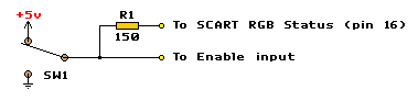
Very simple, just a switch (and a resistor to drop the voltage for the RGB Status pin). It's not very practical but is useful for testing. Make sure switch is of the break before make variety.
Automatic Enable Circuit I (using a PIC microcontroller)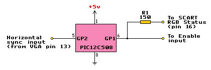
The PIC requires programming, see resources for programmers/software.
Binary - all you need to program the chip (.hex)
Source - the asm source code
This is the ideal Enable circuit. The Horizontal sync line is monitored by the PIC, any time it goes higher than ~17khz the Enable line is pulled low along with the RGB Status line (video muting).
Automatic Enable Circuit II (using the PC's Parallel Port)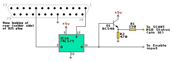
Equivalents... A 74HC75 or 74AC75 should work if a 74LS75 isn't available (if a HC or AC is used all unused inputs must be connected to Vdd(+5v) or Ground). Any general purpose NPN transistor (2N2222, 2N3904, PN100, etc) will work in place of Q1.
For anyone unable to program a PIC or just wants more control over the TV. The Enable/RGB Status line is controlled by data bit 7 on the parallel port.
The popular emulator front end, ArcadeOS, can toggle this bit automatically on startup. All that is required is adding a line in the config file. If another front end is going to be used then download AdvanceCAB. It contains some very useful utilities, notably AdvanceVGA and AdvancePORTIO. AdvanceVGA is used to change the video mode to one that will display on the TV and AdvancePORTIO is used to write to the parallel port. In the autoexec.bat you would put something like...
vga /c pal.rc    ::sets the video mode
portio 378 80    ::sets data bit 7. 80h = 128 decimal.
portio 37A 1     ::pulse strobe line to load-
portio 37A 0     :: data into the latch register
Automatic Enable Circuit III (with the 74xx123)
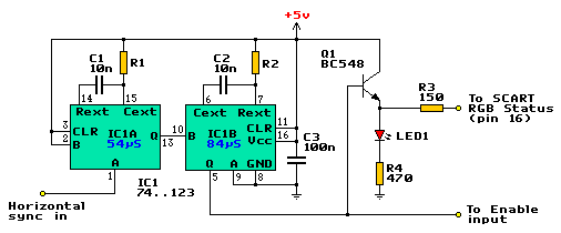
This circuit works like 'Auto Enable I' in that it detects when the sync goes over a certain frequency (18.5kHz ±10%). The circuit consists of two retriggerable one shots. On each horizontal sync pulse IC1A is triggered and generates a 54µS pulse. If H-sync is ~15kHz then the 54µS pulse will trigger IC1B every 64µS. As IC1B is set for an 84µS, the pulse comming in every 64µS constantly retriggers it, keeping the output (Q) at a logic high. If H-sync rises above ~18.5kHz the time between each sync pulse drops below 54µS and IC1A is retriggered constantly. The output from IC1A is just a logic high and as there are no pulses to trigger IC1B it's output is a logic low.
Bastard manufactures! It seems there's no standard 74xx123 out there, many of them use a slightly different 'K' value in their timing formula. The formula is Tw = R * C * K (Tw in seconds, R in ohms, C in farads). Check the table below for different K values along with suggested R1/R2 values for different parts. If the resistor value is non-standard then series/parallel multiple resistors to get close, within 5% is fine.
| PART | MANUFACTURER | K | R1 | R2 |
| SN74LS123 | Texas Instruments | 0.33 | 16k | 25k |
| HD74LS123 | Hitachi | 0.38 | 14k | 22k |
| DM74LS123 | Fairchild Semiconductor | 0.4 | 13.5k | 21k |
| SN74LS123 | Motorola | 0.45 | 12k | 18k |
| 74HC123 | Philips | 0.45 | 12k | 18k |
| CD74HC123 | Texas Instruments | 0.45 | 12k | 18k |
| M74HC123 | ST Microelectronics | 0.45 | 12k | 18k |
| M74HC123A | ST Microelectronics | 1 | 5.5k | 8.2k |
| MM74HC123 | Fairchild Semiconductor | 1 | 5.5k | 8.2k |
| MM74HC123 | National Semiconductor | 1 | 5.5k | 8.2k |
The LED is there for easy testing (you can make sure it's working before plugging hooking it to a TV).
Audio
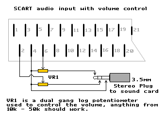
Make use of the (usually) stereo amplifier in the TV. For the volume control to work properly the volume on the TV and sound card should be turned up to their maximum (or loudest you want the volume to go).
Construction
First a thing to do is find a cable with a VGA (HD15) connector already attached, a cable hacked off an old monitor or a VGA cable (cut off one end) is perfect. Sometimes there's enough room inside the connectors to build the circuit, ie the simple circuit can be wired point to point inside the SCART socket and the Parallel Port Enable circuit will easily fit into a D25 shell.
If more space is required then build the circuit on a piece of veroboard or prototype board and mount it inside a small project box. Mount a female SCART connector on the side and drill a hole for the cables to poke through. Something like...
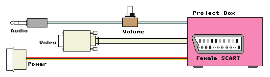
A standard SCART cable has some wires crossed over so make sure you take that into account if wiring to a female connector.
Grounding is pretty straight-forward. Connect each colour's ground to the appropriate SCART pin and connect the VGA's ground wire (pin 10) to any one of the SCART's ground connections (pins 17, 18 or 21). You could connect it to all three if you like but it isn't necessary.
Testing
For a quick test to see if the circuit is working properly run vgatv at the DOS prompt (not windows). Remember to use the /isp (invert sync polarity) switch if testing the simple circuit.
For the Experienced/Brave
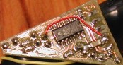
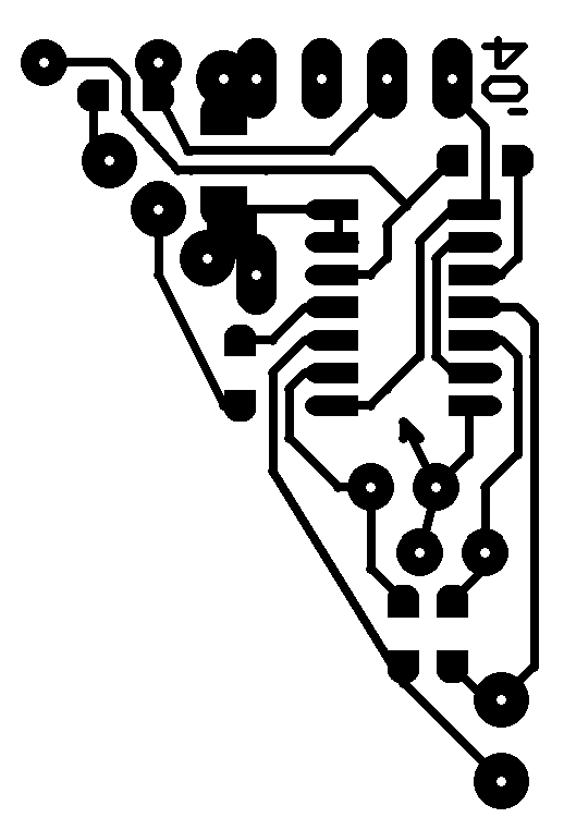
I've designed a PCB for the Enhanced VGA -> SCART + the PIC based Enable circuit small
enough to fit into the space inside a SCART plug. It uses mostly surface mount components
to achieve it's small size. C1 and C2 are tantalum type capacitors and there is an
additional decoupling capacitor mounted between the power and ground pins of the PIC.
PCB Layout - Print at 600dpi
PCB Layout - in Protel Autotrax format
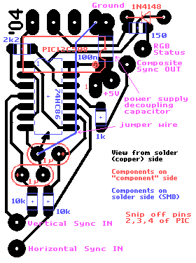
PCB Component Overlay
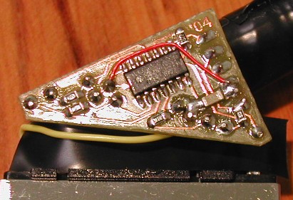
Photo 1 - Solder side (bigger version of image above)
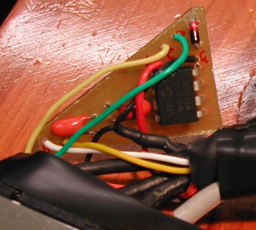
Photo 2 - Other side
Other stuff...
Once the VGA to SCART cable has been constructed there are a few other adjustments that may need to be made to the TV.
Adjusting Overscan
 Overscan
is where the image is scanned beyond the boundaries of the screen. TV manufacturers do
this to eliminate the possibility of black boarders and non-video information appearing on
the screen. Typical overscan is 5 - 10% which is a bit too much for an arcade-monitor-like
usage. Overscan
is where the image is scanned beyond the boundaries of the screen. TV manufacturers do
this to eliminate the possibility of black boarders and non-video information appearing on
the screen. Typical overscan is 5 - 10% which is a bit too much for an arcade-monitor-like
usage. |
On older TV sets the overscan can be reduced by adjusting the Horizontal/Vertical height controls located inside the set. To make this adjustment on newer TVs, enter service mode and make the required adjustments with the remote control via the on screen display. Info on making these adjustments can be found in the TV's service manual (you'll probably have to rent/buy one).
Power
In a MAME cabinet it's desirable to have TV come on when power is applied. Does the TV
have a...
Mains power switch - This type is most ideally suited to a MAME cabinet, simply
switch it on and it will come on every time you apply power.
Soft power switch - These switches are much smaller than the mains type and have
much less travel. When power is applied to these TVs they tend to go into 'standby' mode,
to avoid this, wire a jumper over the power switch (usually a tactile type).
No power switch - These TVs are designed to be turned on and off via the remote
control and do away with a power switch all together. Like the soft power TVs, these ones
usually go into standby mode when power is applied. The way to get it out of standby mode
is by pressing one of the program (channel) +/- buttons. Unfortunately, simply wiring a
jumper over one of the program buttons won't work because the TV will constantly change
channel (brings up an annoying OSD). A circuit to get around the problem....
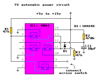
What this circuit does is close the switch for ~3 seconds when power is applied. The
amount of time the switch is closed for can be varied by changing the value of R2. The
formula is T = R2*C1*0.7 (ie. 470*10^3 * 10*10^-6 * 0.7 = 3.29 seconds). This circuit
should be powered by the TV itself. Find a 5-15v power rail that's active while the TV is
in standby mode, if the remote sensor can be located then there's usually a +5v rail going
to one of it's pins. If a suitable source of power can't be found inside the TV then
(after making sure the TV doesn't have a hot chassis) hook it up to the 12v supply from
the PC. Modifying a TV like this requires a basic knowledge of how
TVs work and the associated dangers lurking inside. Unplug and let the TV sit for a while
before working on it.
Resources
Information
SCART
pinouts and information
GamesX's video primer
Tomi Engdahl's VGA to TV
information centre
Build Your Own Arcade Controls
Software
Advance Projects - home of AdvanceMAME,
AdvanceMenu and more.
PC2JAMMA - home of ArcadeOS and Vantage
(I wonder if this works on a TV..)
EnTech's Powerstrip
VGATV
SciTech Display Doctor
and UNIVBE - both are now free to download.
Mon-ARC -
another vga > 15khz TSR
Raine - Another multi arcade game emulator (faster
than MAME in most cases).
![]()
Changelog
1/9/06 - Fixed automatic enable circuit III again....this circuit
really does work now.
30/12/05 - Modified automatic enable circuit III - now based on an
74LS123.
26/8/05 - Finaly started a changelog :). I found out the other day that my
'Simple...' was very poor and didn't function properly (and nobody told me!). It's
now been replaced with the Dodgy Diode circuit which really does work.
Appologies to anyone who built the Simple... circuit. Also added in this update is a
fourth Enable circuit.
17/4/05 - Fixed/added something???
**/**/04 - Rewrote the page.
**/12/03 - Page Created
Tim Worthington, email: eviltim at optusnet.com.au