This is an important step. This is how your control panel will communicate with your computer. There are different ways of accomplishing this, including wiring buttons to joysticks, wiring to keyboards, and wiring to encoders (which simulate computer keystrokes, while virtually eliminating "ghosting" (a combination of keystrokes which tricks the keyboard into thinking that a totally different key has been pressed)). However, since an encoder costs in excess of $100, and a keyboard is often times just lying around in the old computer junk pile. Worthwile to at least try this method first..
Tools needed:
Soldering iron, flux (canít do it without it!), Wire strippers, wire, cable ties.
There are a few ways of doing this hack. Some people like to attach wires right to the traces themselves, and others have keyboards that consist of one large circuit board. Today we are going to attemp this with a basic el-cheapo bubble board. (In this case its a "digital" model RT101)

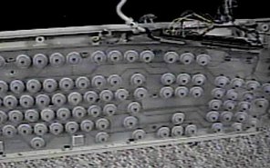
Unscrew and remove the top cover of the keyboard, and carefully pull the keycover off. It should be secured by a series of locking tabs, some of which may be hidden under keys. In most cases, the keys themselves can be pulled off to access the tabs. When complete, the keyboard should look something like the above. Remove the bubble layer, and we are down to the traces.

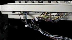
What we are hoping for here is a connector similar to the above. Some trace sheets are bonded to the board, but many have removable connectors. What we really are interested is the board itself. The tracesheets connect to the board in two places. One for the upper sheet, one for the lower. I have seen them all in one plug however, but by looking at the solder points, you should be able to figure out which is which. On the back of this card is the solderpoints for the connector. Here is where we are going to do our connections. Using 22 AWG wire (phone wire), and a 10watt soldering iron, we will construct our interface. You can either follow the traces from the keys you want to use and solder them, or solder them all and figure it out later. This is the route we will take today.

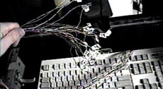
For soldering technique here, I like to have a tiny drop of solder already on the stripped tip of the wire Iím going to connect. Cover both parts you want to solder with a dab of flux, applied with a toothpick. Touch the two sides together, and then apply the solder tip to both wire and contact point simultaneously. With luck, and a bit of trial and error, you should end up with a fairly clean and tight connection. Repeat for all the connections on the upper and lower tracesheets. When complete use your cable ties to secure the wires. You should now have two connections coming off your keyboard.


Double check your solder connections before reassembling your keyboard. You donít want any connections touching! Put your new interface back together, and plug it in. If all went well, you should be able to still use your keyboard normally. Label all of your wires. Keep the upper trace bundle and the lower trace bundle separate. Use google to find a keyboard mapping program. (I used keyscan.zip) Run the program, and start touching wires from the upper bundle to wires in the lower bundle.. Each time a wire is connected, the program should tell you which keypress that represents on the keyboard. Chart these out so that you know which wires are the ones you need. (Note: some wires are used for multiple keystrokes, these wires can be common on your control panel). Solder or connect the wires to your buttons and joysticks, and try it out! If youíre lucky, you wonít have to do to much debugging.
Thatís it! e-mail me with any questions! Iím always happy to help out!
(c)2002 Massmame Inc. All rights Reserved. No duplication without permission.