
LPT-revolution has started !
The latest news is that LPT-switch has gone open source. This means that the source code
files are available for download. If anyone wishes to change anything, or thinks he can
improve the software or thinks it would run lighter in an other language, please feel free
to download my files. They are "as is".
Download now available here
People who want more info on why we use all those diodes & why we use so much of them,
pls visit: http://www.dribin.org/dave/keyboard/one_html/
LPT-reload
The new version of the LPT-switch software is available on www.avsim.com. Only there cuz I
want to be able to see how many downloads this thing gets.
This new version requires the .Net framework so make sure not to forget to download and
install the one that fits your operating system ! You'll need it in the future anyway cuz
all new programs will be more and more programmed in this language. Check the microsoft
website for download.
Make sure again to read the ReadMeFirst.txt file !!

"Full zip" (version v1.3-exe + manual + modules)

(v1.3-exe only).
Shopping list:
1 x "25pin Male LPT-port plug"
5 x 4700 ohm resistors (? => not sure 'bout this yet)
40 x 1N4148 diode
1m cable with at least 13wires
defuse plugs
Next you need some soldering experiance + material (or someone who can do it for ya).
Make the interface as on the pictures below.
!! I'm not sure yet if you do need the resistors !! In case you do need them, here's how
to use them.
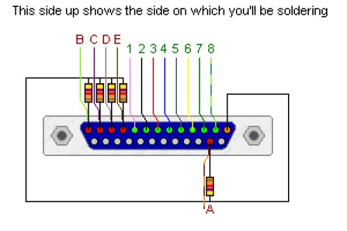
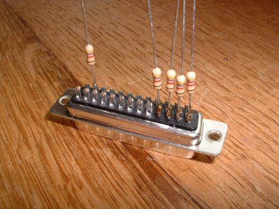
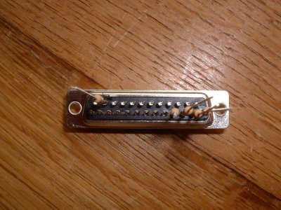
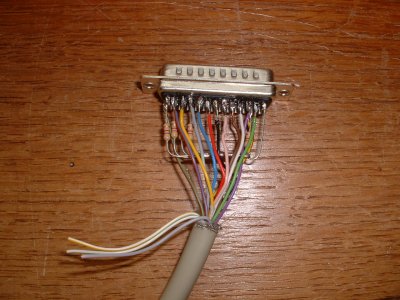
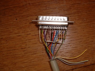
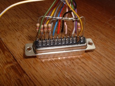
More detail on how to use connect the switches to this will be
illustrated soon. It's quite simple however. The plan is to put between each of the (8)
output lines and the (5) input lines a switch. With on each switch a diode (between the
switch and the input lines / little black stripe on the diode facing towards the switch
and away from the input lines). That's it.
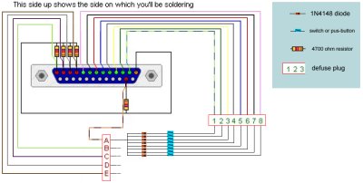
Click the image to get a biger version for nice detail.
The image shows 5 switches/buttons between the A input and 1 to 8 output. Continue doing
the same for B to E.
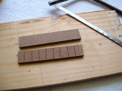
Here's how you might want to make the rest of the interface.
I think the pictures speak for themselves. Only little remark: the wood used is MDF in
which I make small insisions with a saw. The little round collored plugs I use are from
Marklin. You could as well solder the wires from your switches directly onto the pins, but
I thought it might be nice to be able to plug them on and off easely whenever needed.
That's why I use these little wires with the male-plugs. I'll connect the female-plugs to
the wires.
Take care to check which way you have to glue the diodes !!! I was wrong at first and had
to re-do 3 plates! The little black stripe on the diodes should be facing towards the
woodn plates!!
Please note as well that you could also solder 1 diode directly on each switch itself !!
This gives exactly the same result and some people, so I hear, tend to like this better !!
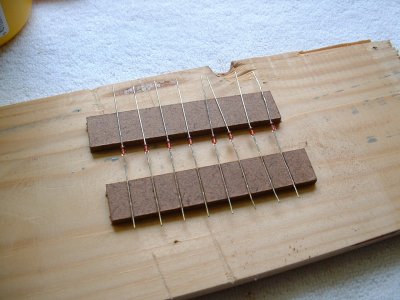
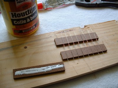
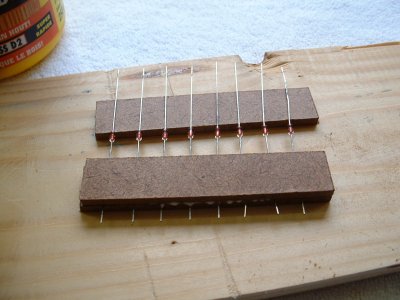
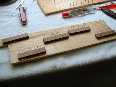
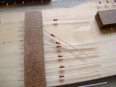
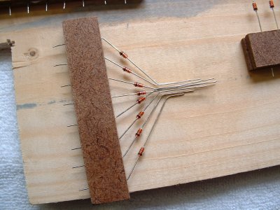
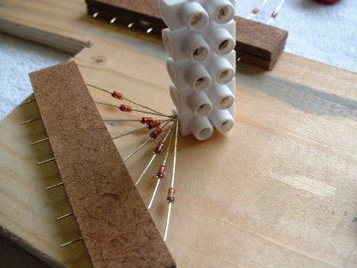
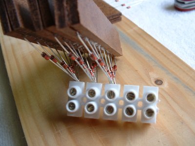
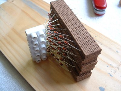
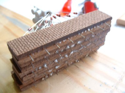
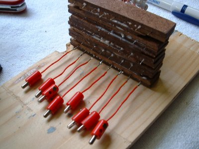
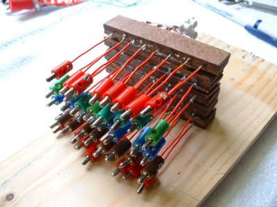
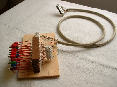
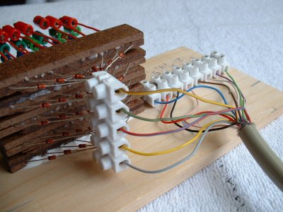
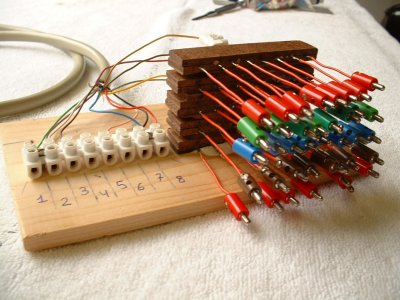
The end result as you can see here above leaves you with outputs 1 to 8
and the inputs A to E represented each time by 1 colored line. So the bottom reds are A
and the blue line for example are C. More pictures on how they will fit into my cockpit
will be here later on.
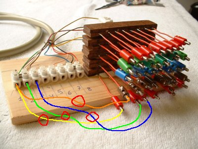
On the picture here above you can see how you connect output 1 with the
first input pin at the bottom of the "matrix-tower" (yellow line). The red
cirkle over the yellow line represents the switch/button which you put in between. This
will be button/switch nr1. Then you do the same from output 2 to the next input pin of the
"matrix-tower" (green line) which will be button/switch nr2. Then comes the next
(blue line) etc untill you have the bottom row of the "matrix-tower" fully used.
(8 buttons/switches). Then you start again from output 1 to the most left inputpin of the
"matrix-tower" but 1 row higher. (orange line). Continue doing so untill all
"matrix-tower" pins are used and you'll have 5 wires in every output-hol on the
left (white) defuse-plug. I hope this makes it all clear now.
Now all you need is the software.
This program requires NOTHING more. So not even FSUIPC to work. It will send out
key-presses as if you would hit them on a keyboard.
Download the software for free at the top of this page now !!
Some new notes:
1) Someone asked if it was OK to solder the diodes to the switches/buttons instead of
making the matrix-tower. Sure, this can be done. Just make sure to solder the right way
around.
2) Someone asked if it would be a good idea to solder the resistors near the matrix-tower
instead of on the LPT plug itself. Sure! If you find a normal LPT cable with a 25 female
pin connector you can do that. This has the big advantage that your plug which goes into
the PC looks clean and nice and can easely be pulled out of the LPT-port.
!! Warning !! There was AGAIN a bug in v1.2 of
the software !! Please if you have v1.2 download the patch zip with the new exe file
inside. If you are a NEW USER, feel free to download the normal file without the patch. It
contains v1.3 of the file without the bug.


