|
.: Optical Coin Sensor and Circuit with
I-PAC connections
This circuit project was developed and submitted by Alan Kamrowski II. The optical coin sensor and circuit here will allow you to get perfect coin detection from your coin door to an I-PAC. I tried two different mechanical coin switches and no matter how I tweaked the switch wire on them, they were terrible at detecting the coin properly. With the switch wire too much in the path of the falling coin, the coin would sometimes bounce off the switch wire and report 2 coins. With the switch wire too little in the path of the falling coin, sometimes the coin wasn't detected at all. When I tried to bend the switch wire some place in the middle, I would get both missed coins and double reports. The best accuracy I could get with either mechanical coin switch was about 1 error in about 25 coins. Perhaps this is typical for mechanical coin switches, I am not sure. Maybe arcade operators had their switch wires tweaked so that 2 coins would be reported more often than no coin reported just to keep customers happy. I would never charge anyone to use my MAME cabinet, but I still want the coin switch to work accurately after spending so much on the project. It occurred to me that by detecting the coin dropping through the coin chute without actually touching it that I could eliminate the coin bouncing double reporting issues. Also, if I had the sensitivity set high enough, I should never miss a coin. So with this in mind, I set out to build a custom optical coin circuit that would interface with the I-PAC keyboard encoder. It took many posts to sci.electronics.design and my basic electronics book, but here is the final sensor and circuit.
|
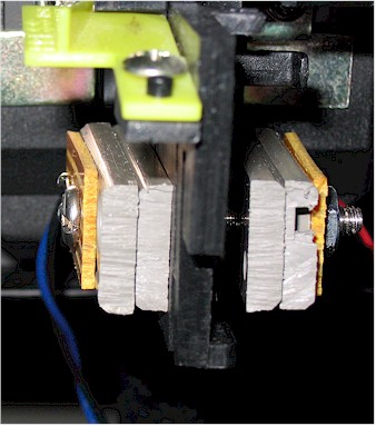
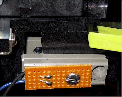
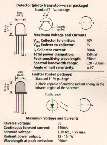
The Optical Coin Sensor On the parts list, there is a matched infrared emitter (LED) and detector (Phototransistor) that need to be assembled into something you can mount to your coin door. The place where the mechanical switch wire was located (before you remove it!) is the perfect place to shine the LED across to the Phototransistor. Once you have the spot picked out, it is just a matter of figuring out how to mount these two components to your coin door. Take note that the LED and Phototransistor look alike and can be easily confused. The darker colored component is the emitter (LED) and the clear colored component is the detector (Phototransistor). Older Radio Shack documentation is INCORRECT about this, but I did find some newer style packaging that is correct (pictured below). What I did was cut a couple of pieces of component board (is this called perf board, or pc board?) to mount the components to. I also found a couple of old plastic drive rails and cut them down to use as spacers to make sure the LED/Phototransistor didn't protrude into the coin chute. With a hole drilled in the same spot on both component boards I could be sure that the components would line up perfectly.
Each component requires two wires. The LED (darker colored) has an anode (longer pin) and cathode. I connected a RED wire to the anode, and a BLACK wire to the cathode. The Phototransistor has an emitter (longer pin) and collector. I connected a BLUE wire to the collector, and a BLACK wire to the emitter. These 4 wires will be run to the circuit board.
|
|
The Circuit The circuit itself has the task of looking for the light to be blocked and indicating to the I-PAC that a coin has been detected. The amount of time a coin will block the light while falling is not long enough to trigger the I-PAC, so a 555 timer IC chip is used to generate a reliable 120ms pulse. The circuit uses 5V right from the I-PAC and needs very little current (<5ma total). Here are the parts of the circuit:
Timer (R1, C1, C2, U4, and R7) - The R1
and C1 combination control how long the timer will stay triggered.
The 10K and 10uF combination will result in about 120ms. I'm not
sure what the C2 does except that it is included in the 555 circuit
example, I am actually using a 0.001uF and it works fine. The 555
circuit is triggered when pin 2 goes low. When the phototransistor
sees light, it allows current to pass through it which will keep pin 2
high and also allows 0.5ma of the current to go to ground. As soon
as the light is blocked, the phototransistor no longer allows the current
and pin 2 will go low because it is then hooked to ground via the R7
resistor. This grounding will set off a timed event where pin 3 will
go high for 120ms. Switching for I-PAC (R6, Q1) - The I-PAC normally has its GND and COIN1 lines connected to trigger a key. We are using a NPN Transistor to allow the COIN1 line to go to ground when the timer has a high output. The R6 resistor is used to keep the current between the 555 and transistor from being excessive. As soon as the output of the 555 goes high, the transistor allows the COIN1 to go to ground and triggers the I-PAC. Here is a schematic of the circuit:
|
|
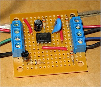
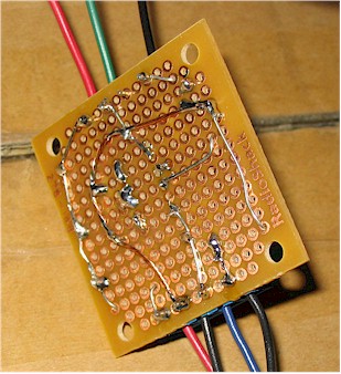
Board Layout and Testing On the left side of the board, the terminals from front to back are : COIN1, Not Used, GROUND, 5V. On the right side of the board, the terminals from front to back are : Phototransistor Emitter (BLACK), Phototransistor Collector (BLUE), LED Cathode (BLACK), LED Anode (RED). You can get the 5V and GND signals right off the I-PAC via its LED header. Once you put the components on the board, connect them using the schematic above and you should be all set. When done, add some nice PCB mounting feet and mount to your cabinet!
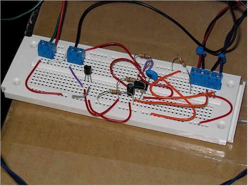
It is always a good idea to test everything out before you go through the trouble of soldering! Here is a picture of my test board and this circuit:
|
|
Parts List and Costs The parts to build this are available at Radio Shack using this parts list: 276-142 Matched Infrared Emitter and Phototransistor Detector $2.99 276-1723 LM555 Precision Timer - 8 Pin DIP $1.29 271-1335 10K 1/4W Resistors $0.99 276-1617 15 NPN Transistors $2.49 272-1025 10µF 35V 20% Radial-lead Electrolytic Capacitor $0.99 272-1065 0.01µF 50V 10% PC-Mount Capacitor $0.99 276-148 Dual Mini Board $1.69 276-1388 2-Position PC Board Terminals $2.29 ------ $13.72 |
|
Reference Links I-PAC - www.ultimarc.com Many helpful people in the sci.electronics.design newsgroup. |
|
Oscar Controls |