|
.: Super Bright LED driver with
I-PAC connections
This simple circuit was built to allow super bright LEDs to be used in my MAME cabinet. There are connections for Num Lock, Caps Lock, and Scroll Lock (controlled by I-PAC) and nine always-on LEDs. Although the I-PAC supports standard LEDs via its onboard LED connections, standard LEDs are fairly inadequate for internal button lighting and other cabinet lighting. Super bright LEDs have many advantages over incandescent lights, including much lower heat output and a nearly limitless lifespan. Super bright LEDs are designed to operate with a 15-20mA current, so a secondary driver circuit would be required because this current exceeds what is available through the I-PAC. In my example the I-PAC isnt powering the
LEDs, but it is still controlling the keyboard LEDs by connecting them
to a general purpose PNP transistor. This is accomplished by connecting a
wire from the appropriate button inputs from the I-PAC to the base lead of
the transistor. The correct I-PAC button inputs for LEDs are as follows: In MAME the keyboard LEDs are typically
used in older classic games (Tempest, Centipede, Missile Command, etc.)
and assigned as follows:
|
|||||||||||||||||||||||||||||||||||||||||||
|
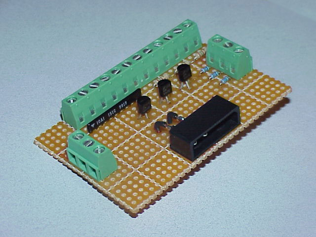
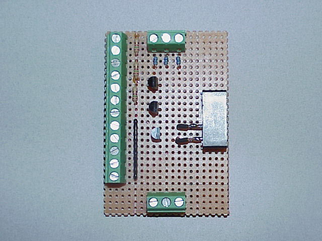
In lieu of a true electrical schematic, I drew
more of a physical one. Hopefully this will be less confusing to the
not-so-electrically-inclined folk such as me. :)
|
|||||||||||||||||||||||||||||||||||||||||||
|
Supply Voltage and Ground I designed the driver board to be very easy to install into my cabinet. The use of screw terminals and a common hard drive style power connector allow this board to be installed with minimum fuss. I had considered using an A style USB receptacle for the power connection, but I settled on connecting the driver board directly to the PC power supply instead of the motherboard in case there was a short on the board. A safer design for this circuit may be to include diodes if you go with a USB connection. Due to the parallel connection of the LEDs, all the cathode legs can be connected to a single ground wire. I opted to use a 3 position terminal block in case I wanted to run a separate ground wires to the control panel and coin door locations, for example. The +12V and second Ground pin was removed from the power connector on the driver board because they were not needed and I didnt want bare pins sticking out (Murphys Law .). Note that the always-on terminals could be used for more than just LEDs. They could be used to power trackball optics connected via a mouse hack if needed.
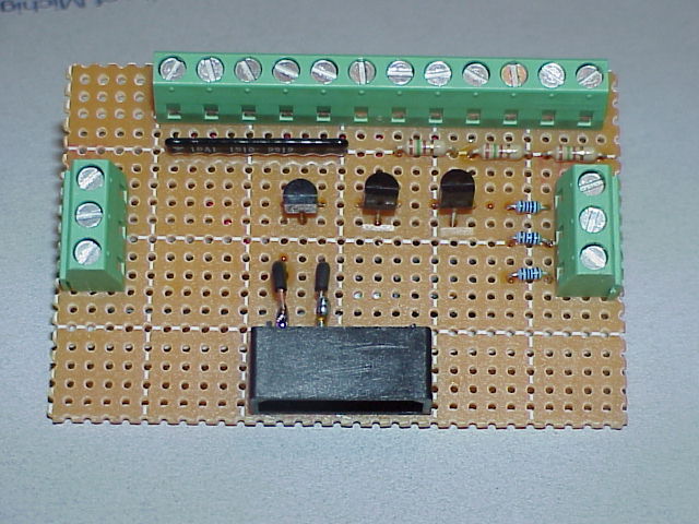
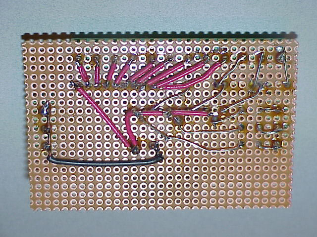
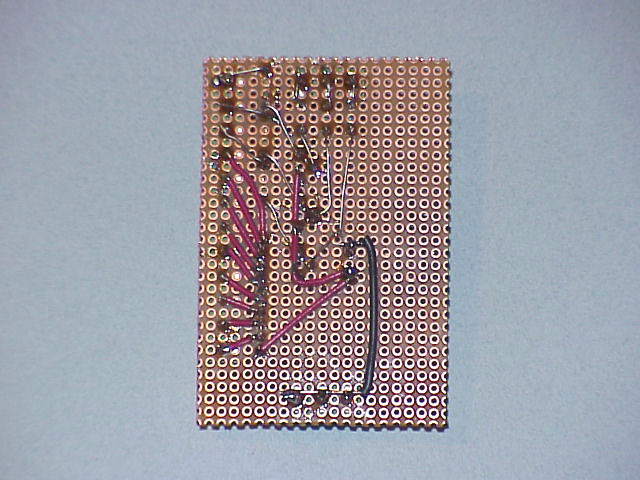
The image on the right is mirrored so the connections can be easily matched to the components in the left photo.
|
|||||||||||||||||||||||||||||||||||||||||||
|
Calculating the Resistor Values The value of the resistors used for limiting current to the LED is determined by the style of LEDs used. In my example, I set up the driver board to operate Red super brights @ 20mA. To determine the resistor value you need, first subtract the LED forward voltage value from the supply voltage value. Then you divide that number by the LED operating current to give you the limiting resistor value in Ohms. This is how mine looks:
A possible enhancement to this driver circuit would be to have a couple of banks of different value resistors, and by moving jumpers the board could support different types of LEDs. Hmmm :)
|
|||||||||||||||||||||||||||||||||||||||||||
|
The Transistors Any style of PNP transistor should work in this circuit. The ones in my circuit were used because I already had them. Perhaps there is a more correct transistor to use for this function, but the general purpose 2N4402s are working just fine. The emitter lead is connected directly to the supply voltage (+5V), and the collector lead is wired to the current limiting LED resistor. A 1K resistor was included in the connection coming from the I-PAC to limit the base current to 5mA which is quite a bit below the rated maximum value for this transistor. As with the transistor, this particular value of resistor was used because I already had them.
|
|||||||||||||||||||||||||||||||||||||||||||
|
Costs While I already had quite a few of the parts for this circuit, I have put together a cost table based on current unit prices if you were to purchase the components. I chose to use www.mouser.com for pricing (except the perf board), but other large electronics retailers such as www.newark.com and www.digikey.com should be very similar. Expect to pay more if you shop at Radio Shack for all these parts.
You can see that more than half of the cost of my driver board is in the screw terminals. Although they arent necessary for operation of the circuit, this is how I wanted to connect my LEDs. To save a few dollars, the LEDs could be wired directly to the limiting resistor leads.
|
|||||||||||||||||||||||||||||||||||||||||||
|
The image on the right is mirrored so the connections can be easily matched to the components in the left photo.
|
|||||||||||||||||||||||||||||||||||||||||||
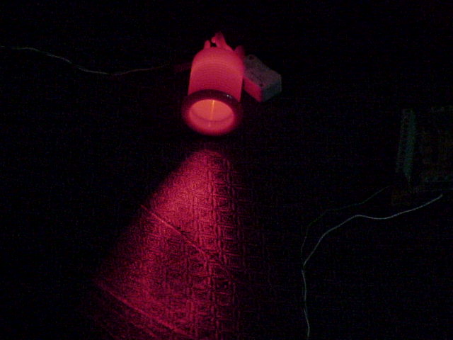 Red LED in red button (1.9V 1300mcd) |
 Red LED in red button (1.9V 1300mcd) |
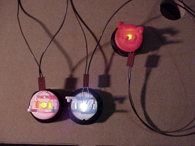 From left to right: Red LED in white button (1.9V 1300mcd)
White LED in white button
Red LED in red button |
|||||||||||||||||||||||||||||||||||||||||
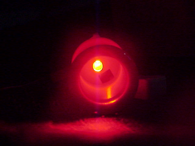
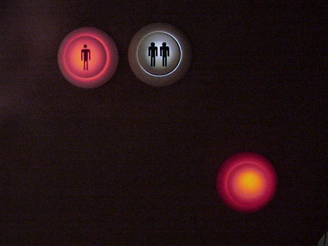 From left to right: Red LED in white button (1.9V 1300mcd)
White LED in white button
Red LED in red button
|
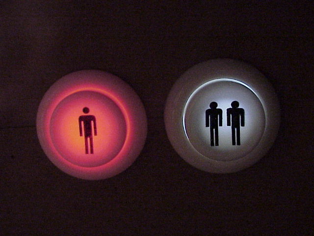 From left to right: Red LED in white button White LED in white button The P2
button is actually a WICO brand. |
||||||||||||||||||||||||||||||||||||||||||
|
Reference Links I-PAC - www.ultimarc.com Erik Ruud -
http://erikruud.freeservers.com/arcade/buttons.html Carsten Carlos -
http://www.retrospieler.de/
|
|||||||||||||||||||||||||||||||||||||||||||
|
Oscar Controls |
|||||||||||||||||||||||||||||||||||||||||||