Notes:
1 - You'll notice that the box shown on these pictures is much more complex than it should be. The reason is that it will house another circuit that will switch between 2 RGB sources, being one of them my teletext decoder's RGB output which also has a Blank signal, used to merge the teletext with the original live picture. This functionality needs yet more circuitry, thus the bigger box and wider room needed. Not to mention plugs.
The ones used right now are the DC plugs (bottom one is 12VDC out, for the decoder), the S-Video plug and the top golden RCA plug and the top VGA plug.
2 - Because of hurry, my own circuit is buggy. I'm still wondering how it hasn't blown up yet :-) Anyway, while checking the PCB to see if I could optimize the size and layout of the board, I discovered that there was an error, which I fixed without changing too much the general layout, so the pictures here more or less reflect how it will look in the end.
3 - You can also notice that some capacitors are struggling for space. Again, the PCB was drawn in the first place without me having them so I couldn't guess the space they would use. The PCB files on this page have all this fixed.
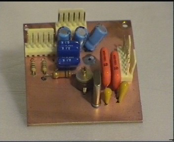 | 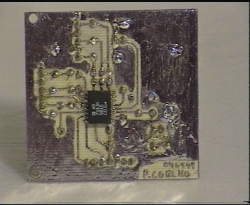 |
| 1-Component side | 2-Solder side |
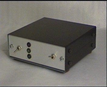 | 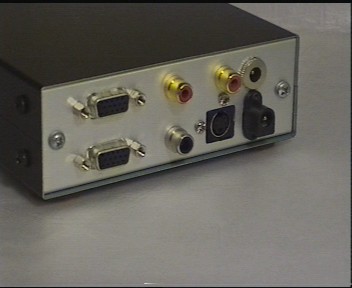 |
| 3-Case front view | 4-Case, back view |
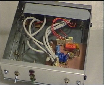 |
| 5-Case top |