For anyone unfamiliar with what RGB video is see this Video Primer.
SCART pinouts and signal info can be found here.
SCART (aka Peritel or Euroconnector) cables for home video game consoles
aren't standard, they are different for each console. The manufacturers have taken full
advantage of this and, in what I assume is an effort to save a few cents, often place
necessary components (esp. coupling capacitors) of the RGB output circuit inside the SCART
cable. Since only a small fraction of people who own a console use/require a SCART cable
it slightly reduces the overall cost.
This page contains circuit diagrams to aid anybody wanting
build/repair/adapt these cables, as well as pinouts and a short description of the RGB
video output (75 ohm driver) circuit. Enjoy...
Notes
TVs with SCART inputs are only common in Europe and Australia (mainly
because we share a similar TV standard (thus TV designs) with most of Europe and the TV
manufactures just leave the connectors in place). If you are from a somewhere where TVs
with SCART inputs are rare then don't despair, some of the upper market TVs offer RGB
input in the form of 4 phono sockets, one for each colour and one for composite sync. If
such a TV can't be found for a reasonable price, then look around for an old RGB computer
monitor that is compatible with the TV horizontal scan frequency, such as the commodore
1084 monitor. Alternatively, if a suitable monitor can't be located and you're good with
electronics, then consider building a SCART to
arcade monitor adapter.
The SCART spec states that to switch to RGB mode the CVBS Status pin must
be fed 12V and the RGB Status (aka Fast Blanking) pin be fed 1-3V. Some games consoles
only output 5V which may or may not be adequate. If the TV doesn't switch and there is no
way to manually force a 'video mode' (such as a button on the remote control) then an
external 12V supply may be required. In cases where the TV is a widescreen model or has a
widescreen mode feature, applying only 5v to the RGB Status pin may force the TV into 16:9
widescreen mode.
In the diagrams I have drawn all the SCART ground pins connected together.
This isn't required but it's a good idea to connect to at least two ground pins (usually
17 and 18). If you're using mini-coax to connect the RGB video (recommended if the cable
is going to be long) then ground pins 5, 9 and 13 provide handy places to solder the
shield. The reverse applies to the console end of the cable. I've only drawn one ground
connection but it may be a good idea make use of other ground connections (if there are
any).
Cables which run video and audio signals together without a seperating
shield around the audio wires may cause an annoying 50 or 60hz buzzing sound in the audio
which vaires in volume with the picture content. This is caused by the capacitive coupling
of the two wires running next to each other. The longer the cable is the more capacitance
between the wire. The best way to avoid this is to run a seperate cables for audio and
video join them together again at the SCART end.
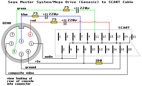
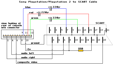
A/V output comes from an 8 pin female "U" DIN connector. Pinouts are: 1 audio, 2
ground, 3 composite video, 4 +5V DC, 5 green video, 6 red video, 7 composite sync, 8 blue
video. RGB output circuit: Sony CXA1145 video encoder IC - outputs come straight from the
chip.
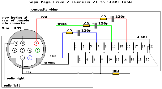
A/V comes from a female 9 pin mini DIN connector. Signals are the same as the original
Megadrive with the addition of stereo audio. Pinouts are: 1 blue video, 2 +5V DC, 3 green
video, 4 composite video, 5 composite sync, 6 audio mono, 7 red video, 8 audio left, 9
audio right, and the metal shield is ground. RGB output circuit:
CXA1145/CXA1645/KA2195/MB3514 video encoder IC - outputs come straight from the chip.
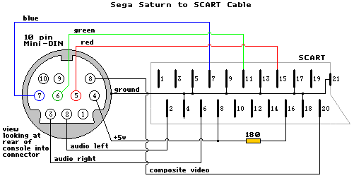
Connector is a 10 pin mini-DIN type. While it's a standard connector, it's extremely rare
so don't expect to be able to buy one from the local electronics shop (or anywhere for
that matter). The Saturn puts out luma/chroma (s-video) as well as the usual RGB/CVBS.
Pinouts: 1 composite sync, 2 audio left, 3 audio right, 4 +5V DC, 5 red video, 6 green
video, 7 blue video, 8 composite video, 9 luminance, 10 chrominance. RGB output circuit:
signal comes out a CXA1645 through a 75 ohm resistor and a coupling cap.
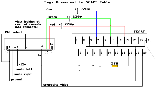
Utilises a proprietary connector for A/V out. Supports CVBS, RGB (TV), RGB (VGA, req.
adapter) and luma/chroma. Pin 7 must be connected to ground to enable RGB. Pinouts: 1
ground, 2 audio right, 3 audio left, 4 +12V DC, 5 +5V DC, 6 RGB (VGA) select, 7 RGB (TV)
select, 8 vertical sync (for VGA), 9 horizontal sync (for VGA), 10 composite sync, 11
chrominance, 12 luminance, 13 composite video, 14 blue video, 15 green video, 16 red
video. RGB output circuit: proprietary DAC.
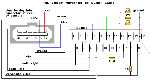
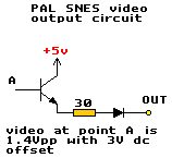
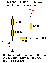
Super Nintendo
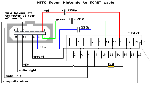
For some unknown reason the RGB output circuits differs between the NTSC and PAL consoles.
As a result the cables are different too (though I somehow doubt Nintendo had any
intention of releasing a SCART lead for the NTSC SNES).
Proprietary A/V connector. Pinouts: 1 red video, 2 green video, 3 +12V DC, 4 blue video, 5
ground, 6 ground, 7 luminance, 8 chrominance, 9 composite video, 10 +5V DC, 11 audio left,
12 audio right. RGB output circuit: here
Pinout is the same as above with the exception of pin 3 which is composite sync instead of
+12V. RGB output circuit: here
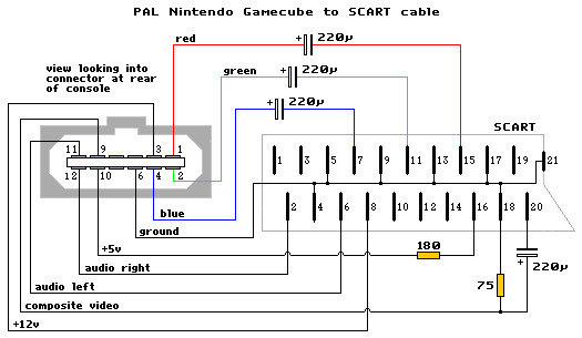
Proprietary A/V connector. Pinouts: 1 red video (PAL only), 2 green video (PAL only), 3
+12V DC, 4 blue video (PAL only), 5 ground, 6 ground, 7 luminance (NTSC only), 8
chrominance (NTSC only), 9 composite video, 10 +5V DC, 11 audio left, 12 audio right. RGB
output circuit: proprietary DAC.
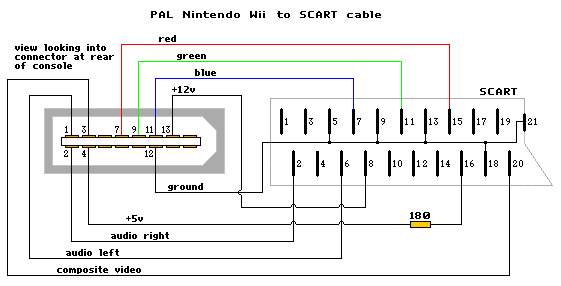
Nintendo Wii
Like the Gamecube, RGB video is only available from the PAL Wii.
Proprietary A/V connector (different to the proprietary A/V socket used on previous
nintendos). Pinouts: 1 left audio, 2 right audio, 3 composite video, 4 +5v DC, 5 ground, 6
ground, 7 red video (luminance/NTSC), 8 mode select, 9 green video (chrominance/NTSC), 10
mode select, 11 blue video, 12 ground, 13 +12v DC. Pins 14-16 are for something called a
Japanese D-Terminal Cable. Mode select pins are normaly left unconnected. When they are
connected together, component video (YUV/YPbPr) will output from pins 7, 9 and 11 in place
for RGB/S-video. The DC voltage on pin 13 will drop to 5v for widescreen games (will it?).
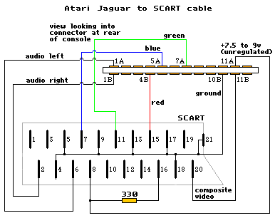
Propriety connector. Pin outputs: 1 ground, 2 audio right, 3 ground, 4 audio left, 5
luminance, 6 composite sync, 7 chrominance, 8 ground, 9 blue video, 10 +5V DC, 11 red
video, 12 green video.
RGB output circuit: signal comes from a CXA1645 and a through a 75 ohm resistor.
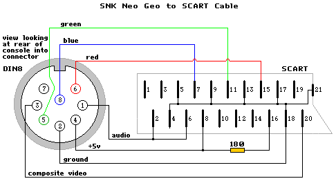
Female 8 pin "C" DIN connector. Pinouts: 1 audio mono, 2 ground, 3 composite
video, 4 +5V DC, 5 green video, 6 red video, 7 composite sync, 8 blue video. RGB output
circuit: signal comes out a CXA1145/MB3514, through a 75 ohm resistor and a coupling cap.
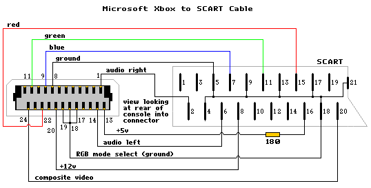
Propriety connector. Pinouts: 1 audio right, 2 audio ground, 3 SP-DIF digital audio, 4
vertical sync?, 5/6/7/8 ground, 9 video output A (blue), 10 video ground, 11 video output
B (green), 12 video ground, 13 +5v, 14 audio left, 15 audio ground, 16 horizontal sync?,
17/18/19 video mode select (ground all three for RGB), 20 +12v (RGB Status), 21 video
ground, 22 video output C (red), 23 video ground, 24 video output D (composite video).
Different audio/video configurations are selectable by maniplating the three video mode
select pins (17, 18 and 19). See the Gamesx
Xbox pinouts page for more info on this. The DC voltage on pin 20 will drop to +5v for
widescreen mode.
Data sheets in PDF format for: CXA1145 - [japanese] ES71145 - CXA1145 compatible CXA1645 MB3514 - CXA1145 compatible (with Y/C driver output) KA2195D - CXA1645 compatible (with no Y/C output), may be
mistaken as SKA2195D
Changelog 16/8/09 - Corrected text descriptions for Sega Master System and Sega
Saturn. Also added a note about audio/video separation. 31/12/06 - Added a diagram for the Wii and corrected the Sega Saturn diagram (left
and right audio were swapped around). Also made a few minor changes to the page. 8/8/05 - Added diagrams for Atari Jaguar and Microsoft Xbox. Jaguar info taken from here. 1/7/05 - Added diagram for the Nintendo Gamecube. Added some
datasheets. Fixed an error in the NTSC and PAL SNES diagrams (had pins 3&4 swapped on
the diagram). I also modified the PAL SNES diagram a bit (the 12V output didn't supply
enough current to feed SCART pin 16). Thanks to David Bielen for the Gamecube related
info. 18/5/05 - Fixed errors in megadrive/master system cable (had it drawn
back-arsewards), neo geo (din 8 connector drawn incorrectly), and pal snes (missing
resistor from video to ground). Info thanks to this Japanese website. 4/5/05 - Page created