MpxPlayer -- MP3 Player Version II
This is actually the third (and probably the last) instalment in the great MP3 player legacy. Starting with the Prototype, continuing with the MP3 Player Project and concluding here.
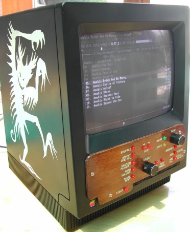
I thought that my Macintosh SE would make an ideal enclosure for something...Another MP3 player? Why not. Now there's a PC in there running Mpxplay, a DOS based audio player.
The player will play audio CDs as well as MP3/Ogg Vorbis audio files from either a CD-ROM or it's internal hard drive. Ease of use is very important here. I think it's pretty good job there, with a good set of controls and a big 80 column display. The controls are designed specially around Mpxplay, taking advantage of some of it's best features and making it easy to create playlists. And there's not a single navigation menu (well...unless you count he file browser) - each button does what it says it does.
-------------technical information below-------------
Cosmetics
I'd heard that Vinyl Colour/Dye paint for car interiors was good for painting PVC/ABS plastics. And it's true! The black paint looks really good and is quite tough. It's certainly not perfect, and I'm sure in a few months time there will be white bits showing through on the edges, but I'm pretty pleased with the result. The artwork on the left side (stolen from the cover of Tromatism's LP) is the original mac plastic showing through. It was done with a simple stencil method: first sand the side flat with fine sandpaper (so paint doesn't seep under the sticker), cut out the design from an A4 sticky label, stick on, paint over, peel off when dry.
The front panel was made from 3mm plywood. There labels were done with dry-transfer lettering. I had a really hard time finding a supplier of small white lettering. No one local seems to sell the stuff and most of the online suppliers of the stuff wanted huge amounts of money for either the lettering or the postage. After lots of emails I finally found an online shop that would sell me a packet of the stuff. They're called Minute Man Electronics. I thought I'd mention them because they were really helpful and didn't try to rip me off with excessive postage fees.
Computer Hardware
The computer consists of an Acorp SIS miniature 486 motherboard with an IBM (Cyrix) 5x86-100 CPU and 8MB of RAM. There are three ISA expansion cards: A Sound Blaster AWE64 soundcard, a 3com 3C509c network card, and a Cirrus Logic video card. The expansion cards can't be plugged directly into the motherboard due to the way it's mounted so they're mounted on a sort of 'riser board' built from the ISA slots chopped off a discarded motherboard. This 'riser board' with three cards mounted on it was then screwed to a block of wood and the block of wood screwed to the chassis. Wires run down to one of the ISA slots in the motherboard below.
There are two drives, an apple slot loading 24x CD-ROM drive (from an IMac!) and a 4GB hard drive. The CD-ROM drive has a non-standard 50pin connector instead of the 40pin type expected on ATA devices. Pins 1 to 10 are for power and CD audio output and pins 11 to 50 are the standard ATA pins shifted up 10. I simply added a 50 pin connector to a standard IDE cable and left pins 1-10 unconnected. Power gets into the drive via a male molex connector I soldered onto the back. I also ran a wire inside the drive to a switch on the mech that detects when a CD has fully loaded. This wire goes to the connector PCB on the output where the signal is buffered with a couple of transistors and fed to the I/O PCB where so it can be used to light up the eject button (so people don't try to force a CD in when one loaded) and signal the PC that a disc has been loaded/unloaded and it should change the path in the directory browser.
The hard drive is a tiny little 4GB thing because there is an 8GB limit in the bios' HDD routines. I do intend to upgrade it to an 80GB drive in the near future but this bios limitation is causing me problems. There are several ways around it - these include a bios upgrade, overlay software, a controller card or a bios overlay card. A bios upgrade is not an option as there is none available. I've used overlay software in the past but it can cause a lot of problems (can't read data on another computer) and I’ll only use it as a last resort. I do have a hard drive controller card but it's not much use as there no room to put it inside the player.
The solution I'd like to implement is the bios overlay card (such as the Promise DriveMax). This is a small ISA card with only an EPROM and some glue logic. The EPROM contains a small piece of software that is loaded right after POST which replaces the old, broken hard drive access routines (int 13h) in the bios with improved ones that can handle drives up to 128GB. I believe I can remove the EPROM from the card and place it in the boot rom socket on my network card. That way I can have the features provided by the card without taking up and extra (non-existent) ISA slot. The only problem with is that, despite my best efforts, I've been unable to locate one of these cards new or used. If anybody has a card they're willing to sell (or even just a dump of the EPROM) please get in touch!
The computer is powered by the original mac power supply. I had a bit of trouble with this a first due to mac's power supply not having a 'power good' line which goes high only when the power has stabilised. At first I tried tying the power good line to the +5v line and the computer refused to boot. If I turned the power supply on before plugging it into the board it would boot but would corrupt it's CMOS memory when powered down. The solution to add a small, three legged microprocessor reset IC (commonly found in TVs, VCRs, etc) to take control of the power good line. It keeps the line low till the voltage rises to about 4v where the pullup resistor takes the line high. The IC pulls the line low again when the voltage dips below 4v while powering down. Another power related issue caused the video to jitter a couple of times a second. This was fixed by adding a 2200� 10v electrolytic capacitor between the +5v rail and ground on the motherboard.
Computer Software
I wanted to use FreeDOS for the operating system because I'd heard a lot of good things about it recently. Unfortunately, the reality is that FreeDOS is still the buggy, fickle thing it was when I tried it a few years ago. The latest release has a totally buggered up installer that doesn't work at all. The previous release installs ok but tends to lock up or spit invalid opcode errors at you. And this was on three different computers!
It's back to generic old M$-DOS 7.1 as the operating system. The player software is, of
corse, the latest version of Mpxplay (v1.53). It's
been slightly modified to communicate with my I/O controller board (mainly regarding
output). Other programs used include:
DOSLFN 0.40c for long filename
support
SHSUCDX 3.02 CD-ROM
extender
AdvanceVGA 0.11 part of AdvanceCAB
All maintenance and file uploading is done via the FTP server built into Mpxplay.
I/O Controller
All the front panel controls and other I/O functions are handled by a PIC16F873
microcontroller which communicates with the PC over a 9600 baud serial line.
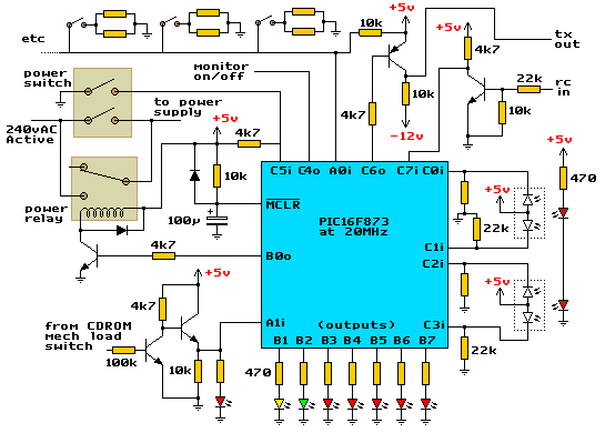
My micro's software features 2 quadrature decoders, a screen blanker, up to 20 pushbuttons
(on a single I/O line) and 13 general purpose outputs (for LEDs, etc). It communicates
with the PC by sending bytes of information which are converted to keyboards actions by
the Mpxplay serial handler. A single byte send to the micro will make a certain output
high or low. The parts for the quadrature encoder were taken from a computer mouse. It's
currently set up to send about 12 bytes per revolution. The pushbuttons each have
different resistor values in series so when one is pressed it forms a voltage divider with
the 10k resistor. From this point the micro measures the voltage and works out which
button was pressed (via a lookup table). The monitor on/off output is used to switch off
the monitor during boot (as the video signal is not yet suitable for monitor consumption)
and after a long idle periods screen blanker will shut the monitor down.
Once the PC has booted, the computer software sends a byte to the micro to activate the power relay. It stays on until the user switches off the power switch. At this point C5i is grounded, the micro sends a byte to the computer saying "get ready, I want to turn you off now" the PC's software saves it's settings, closes all files, then sends a byte back to the micro saying "I'm ready, cut the power". The relay is then switched off along with the power. If the micro doesn't receive this byte from the PC within two seconds, it assumes there's a problem somewhere and switches the relay off anyway. The B0 output also drives a pair of relays located on the PC's sound card. The audio output is passed through these relays to prevent a 'pop' sound coming through the audio on startup and shutdown.
Resource
Microcontroller asm source code 18KB
Video Monitor
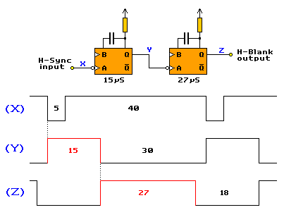
This bit was quite tricky. The Mac SE, like all the early compact macs used a 9" monochrome monitor that operated at a22kHz scan rate. I traced out the circuit of the mac's horizontal and vertical deflection circuits and discovered that the horizontal section is incomplete. What I mean is, inside a standard video monitor there is a horizontal oscillator that drives the horizontal deflection system even when there's no video input. When a video signal is connected the horizontal sync pulses, provided with the video are used to synchronise the horizontal deflection with the incoming video. In the case of the mac's monitor there was no horizontal oscillator, the so called "/HSYNC" line goes through a logic inverter then straight to the base of the horizontal drive transistor. So, in fact, this monitor requires a horizontal drive signal not a horizontal sync signal (as there is no oscillator to synchronise).
To solve this problem I simply used a couple of one shots (74LS123) to reshape the sync
pulse into a drive pulse. It seems to work ok, a more elaborate option would be to have a
local oscillator and keep it in sync with a phase locked loop circuit but I went to the
simple option. The following diagram explains it all. Times are in microseconds. And the
H-Sync frequency is what we want it to be, not what it is (yet).
The vertical section is pretty standard and will operate on a normal negative polarity
sync signal.
The next problem is the scan rate. Standard PC monitors don't scan down to 22kHz so there are no standard video modes that go this low either. I did play around with some EGA cards in standard EGA video modes but found that while the video scan rate was compatible, the blanking times are far to too short for this monitor. This means that the video wouldn't fit entirely onto the screen and overflowed into the horizontal/vertical retrace.
Next, I started playing with a VGA card. I discovered that I could get digital video from the VESA feature connector which was really handy. I played around with a piece of software called AdvanceVGA, part of the AdvanceCAB package of apps by Andrea Mazzoleni. This let me play with the VGA video timing using the convenient modline format rather that attacking the crtc registers myself. Unfortunately, this program has only supports standard VGA dot clocks. That is, 25Mhz, 28MHz, 12.5MHz (25/2) and 14MHz (28/2). I calculated that in order to get 80x25 character display with nice looking 9x14 character cell I'd need a dot clock of about 21MHz. Back to the feature connector and some pins called "dac clock" and "select internal dot clock"...this looks interesting. It turns out that this "dac clock" pin becomes an input when I ground the "select internal dot clock" line. So I try looked up the closest standard crystal value to the freq I want... 22.1184MHz...sounds good.
When my crystal arrived from the mail order supplier (a month later...) I built a simple oscillator around it and hooked it up to the video card. The ArcadeVGA software let me down here, and wouldn't accept the fact that my VGA card really did have a 22Mhz dot clock. I took a look though the source code (the program is open source) and, armed with some rudimentary c skills, hard coded the thing to use the external 22MHz clock and bypassed a check on dot clock accuracy. Works well now :)
Now, I have a good 80x25 1-bit monochrome text display on the monitor but that's still not good enough...I need a few different levels of intensity for this monitor to be useful. Time to design a new video amplifier for it. The original design used a single transistor that could be switched on or off, no linear region. My design (actually not 100% my design, it was copied from another monitor with the component values changed to suit this one) accepts 2-bit digital video giving 4 different possible intensities (white, light grey, dark grey, off). It uses a linear cascode configuration on the output with a BC546 transistor at the top and a BC548 on the bottom (I forgot to print that on the circuit diagram). Being a linear design, it need a high power supply voltage. I wrapped 15 turns of wire around the flyback transformer's core and connected it in series with the +30v video amp supply winding, bringing the video amp supply to +43v. I also upgraded the filter capacitor on the output to prevent any unwanted explosions.
Also part of the video system is an 74LS08 quad AND gate mounted on the video card. At the input to each gate is one of the four signals required by the monitor - h-sync, v-sync, video 1 (PG), and video 2 (PB). To the other input on all the gates is a control signal from the I/O controller which can turn the monitor off and on as it sees fit (used for keeping the monitor off during boot and as a hardware screen blanker)
Resources
Improved Video Amplifier circuit diagram 116KB
AdvanceCAB
1.1.3 source code 500KB (from sourceforge)
AdvanceVGA 1.1.3 binary, modeline file and partial source (req.
AdvanceCAB to compile) modified by me 10KB
Macintosh SE horizontal deflection circuit diagram 104KB
Macintosh Classic horizontal deflection circuit diagram
95KB
Macintosh Classic II Developer Note PDF - contains video
timing information 287KB
Classic Mac Tech Info PDF - tech info on mac plus 102KB
![]()
Page created on 20/2/06