|
Adding extra
buttons to a HotRodSE
PLEASE NOTE: I read this from the
Unofficial HotRod Support Site
so thanks to the people who discovered and documented this great trick. I hope this step-by-step guide will make it easy to
follow and reproduce.
Although this is a fairly easy task to accomplish, some electrical knowledge is required, and I guess it's possible to break
your HotRod so don't do it if you're not confident you know what you're doing. Also don't blame me if you screw up your
HotRod and/or PC.
Step 1:
Turn your HotRod over and take off the back cover. Now locate the connector on the HotRod keyboard encoder board (where you
plug the PS/2 cable) with only two wires coming from it (should be on the left as you look at it, but the right hand side of
the HotRod).
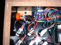
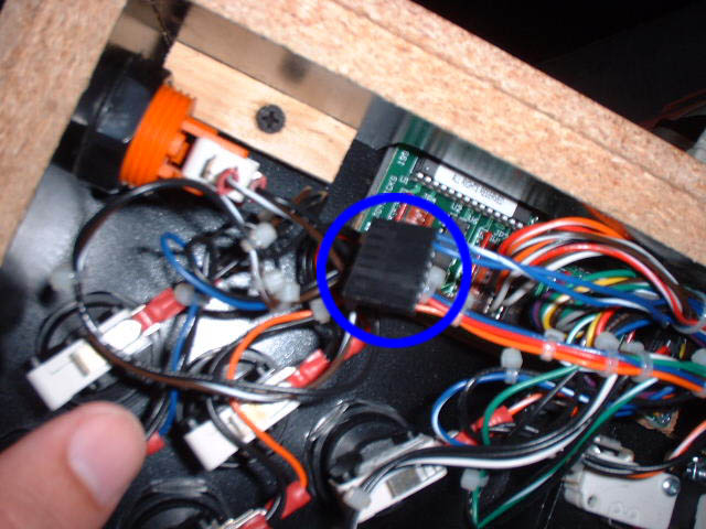
Step 2:
Make a note of the colours and positions of the two wires going to the plug (mine were Blue/White at the top and Blue for the
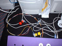
2nd one). Remove the plug (SEE PHOTO) and you will see 8 pins. These are what we are interested in connecting to for the
extra buttons. Now you can either buy a replacement plug to connect to or solder directly to the pins. I chose to get a new
plug and I'd definitely recommend going this way. I bought mine from
Maplin,
part no's
YW23 (PCB Latch Housing 8-Way)
&
YW25C (PCB Terminal).
Step 3:
Here is a description of which pin refers to which keystroke
(M.A.M.E. defaults in brackets):
PIN 1
- X (P1 Button 6)
PIN 2
- [ (P2 Button 6)
PIN 3
- ESCAPE (Quit)
PIN 4
- ENTER
PIN 5
- TAB (Menu)
PIN 6
- F1 (Various)
PIN 7
- F2 (Various)
PIN 8
- P (Pause)
NOTE THAT PIN 1 IS NEAREST TO THE TOP OF THE HOTROD (PINS 1 & 2 ARE WIRED UP AS STANDARD).
Decide which buttons you want to wire up. I opted for just ESCAPE, TAB and 'P', but wired up all of them just in case
I decide to add any of the others later.
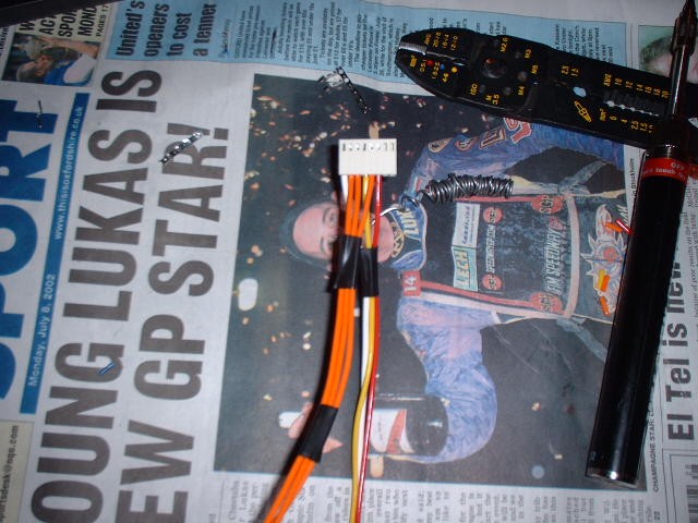
Now take some suitable wire (again I got mine from
Maplin)
and crimp/solder the terminals for use in the new plug. I chose
to solder them, but crimping is fine if you have a suitable crimping tool. The terminals must then be inserted into
the main plastic plug (make sure you get the terminal the correct way round). Obviously, also make sure you insert the
terminals in the desired positions for each button. I found it a good idea to use different colour wire if you have it and
also label the wires with some masking tape with which wire refers to which button. I used orange cable for the three
buttons I am not using at the moment. Make sure you leave PINS 1 & 2 free, for the existing wires in the HotRod.

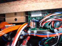
Step 4:
Go back to the HotRod and cut the existing plug from the end of the two wires (for PINS 1 & 2). Now solder or crimp
terminals on these two wires ready for the new plug. Insert the terminals into the new plug as before. You can now plug
the new plug onto the HotRod board.
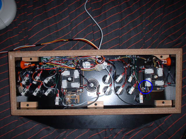
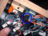
Step 5:
All you need now is a Ground (GND) connection for your new buttons. Look for black wires daisy-chaining from microswitch-to-microswitch. I picked a switch that only had one black wire coming from it - it happened to be the Player 1 Joystick Left
switch. Just remove your chosen wire, cut the plug off and strip the end, twist together with your new Ground wire and
re-crimp a new blade connector on (I found it difficult to obtain a 0.187" connector so just used a 0.25" one - it worked
just fine). Re-connect the blade connector to the microswitch. At this point I
also tucked away the 3 unused (orange) cables which I may or may not choose to
wire up later.
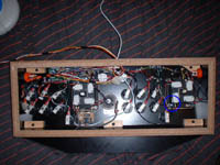
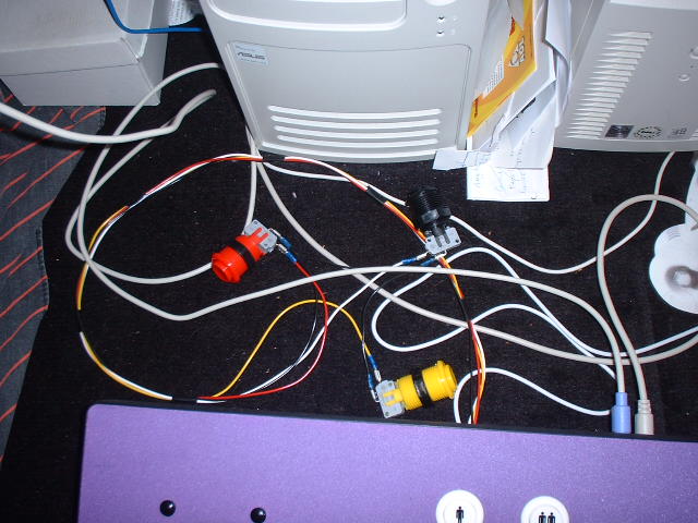
Step 6:
That's the hard part done. The next part is up to you really, and where you want to locate the buttons. I
was planning to
build a cabinet and incorporate my extra buttons within the cabinet (not the HotRod
itself) so I used long wires to exit the
HotRod. I tried to route the wires neatly, and taped them together with small pieces of insulating tape
(cable ties would be better). I also tied a
small 'knot' in the cables to stop them from being pulled too much through the hole in my HotRod (Note I had already drilled
a large hole from when I fitted my
Oscar Model 1 Spinner
, do the same if necessary).
Finally I crimped blade connectors onto the ends of the cables and connected them up to some buttons I got from
Ultimarc.
Use the one Ground wire for all buttons (daisy chain from
one microswitch to the next). Job Done

Load up M.A.M.E. and check that all works OK. Mine worked perfectly first time but if not check all your connections and try again. Good luck...
(last edited on 14/01/05)
|