|
Hacking a
Mouse (for a Happ Trackball)
PLEASE NOTE: This process worked perfectly using the Micro$oft IntelliMouse. It did not work with a Logitech mouse that I
tried, and the chances are it won't work with some other mice. Also, there are different revisions of the IntelliMouse, so
beware that if you have one, it may behave differently than mine.
Also note that I was very careful, and connected this to an old (worthless) PC
to make sure it worked (and didn't screw up my PC). Please beware that you could
probably damage your PC by doing something wrong so don't blame me if you break anything.
This process should work for almost any optics-based arcade
controller, eg trackball, spinner, 360 degree steering wheel, optical rotary
joystick etc...of course you'll need to figure out the differences between the
Happ optic board and whatever board you are using.
Step 1:
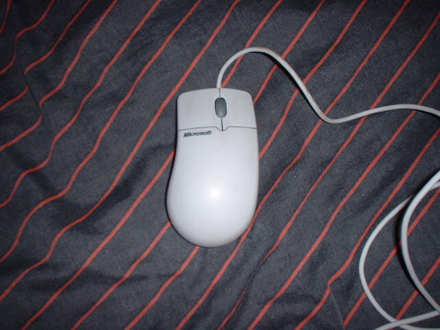
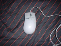
Firstly, select a suitable victim. DO NOT PICK A LOGITECH MOUSE - I spent a whole night trying to get one to work and
failed. Big thanks to Kelsey from
Oscar Controls
for informing me that Logitech mice do not usually work with
arcade optics. I ended up using a Micro$oft IntelliMouse which I got second hand for £5.
Step 2:
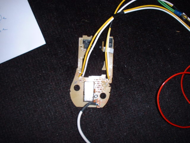
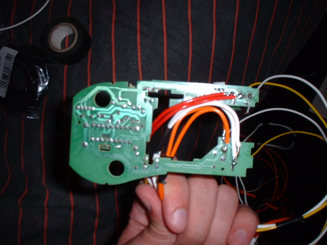
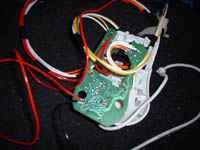
Now take apart the mouse fully and locate the two detectors on the circuit board. These are usually black and have three 'legs', and should be located closely to a (probably) clear LED (emitter). We are only interested in 2 of the 3 legs, so identify the one to ignore. I did this by following the track on the circuit board - one of the legs should join up with one of the legs of the nearby emitter. It will probably also make its way to the other detector. This pin supplies an input to the detector, which we do not require since we're using the optics on the trackball. In the case of my IntelliMouse, the pin to ignore was the centre one, but this probably differs among other makes of mice.
You need to unsolder the detectors from the mouse board completely, and solder some wires to the 2 pins (where the emitter
used to be) that we are interested in. For neatness I fed the wires through from the top of the mouse board, but it doesn't
really matter. It's probably best that you label the pairs of wires as 'X' and 'Y' at this point, referring
to the mouse's Axes.

Step 3:
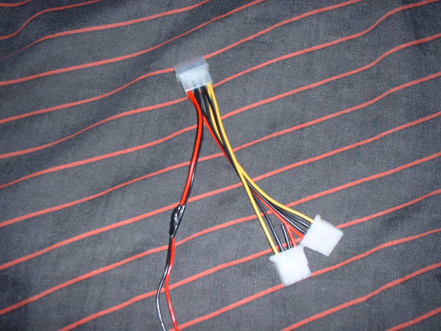
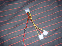
Next you need to get some power to the Happ optical circuit board. I'm sure it's possible to get 5v from the mouse board,
but I chose to tap into a disused disk drive connector (inside the PC). The red wire supplies 5v, and pick one of the
black wires for Ground (GND). If you don't want to cut the drive plug from the
lead, then use a Y-splitter cable.
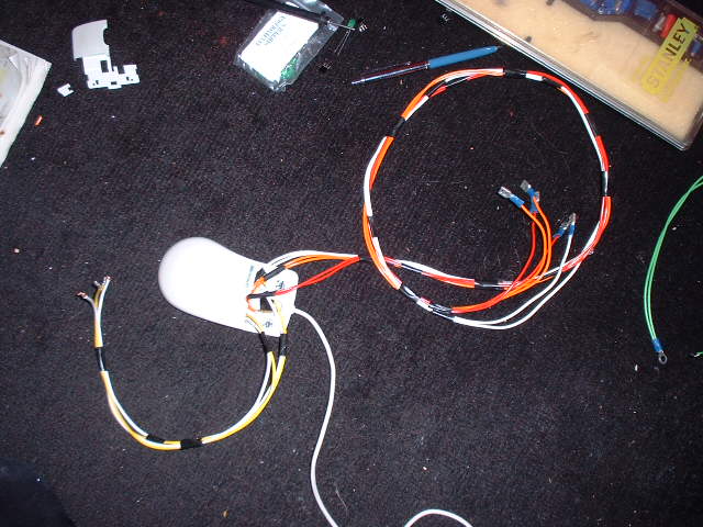
Now go to your trackball, and cut the white plug from the cables coming from the two optic boards. Join the two red wires
together, and also the two black wires, and connect these to your power leads coming from the PC. I used blade connectors so it can be easily disconnected if necessary.
UPDATE: I since sourced +5v from the mouse board using a
multimeter, and following the tracks on the circuit board.
Step 4:
Now you're ready to connect the mouse board, to the trackball. Take a look at your mouse and trackball, and connect the pair
of wires from the X-Axis on the mouse board (did you label them earlier?), to the X-Axis on the trackball. You should be able to trace the wires from the trackball lead back to the optic boards, and figure out which axis they are from. My trackball had Yellow and Green wires for the X-Axis , and Purple and Blue wires for the Y-Axis (I expect all Happ trackballs are the same but who knows?). Again, I used blade connectors to connect the wires together in case they ever need to be disconnected (Bullet connectors would have been better as I've had to insulate round the blade connectors).
Here are the connections you should have made (assuming the colours are the same as mine):
| Trackball |
Mouse |
| 2x Red |
5v |
| 2x Black |
GND |
| Yellow |
X1 (one of the pins on the mouse board X-Axis) |
| Green |
X2 (the other pin on the mouse board X-Axis) |
| Purple |
Y1 (one of the pins on the mouse board Y-Axis) |
| Blue |
Y2 (the other pin on the mouse board Y-Axis) |
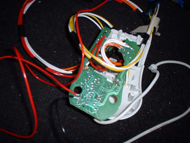
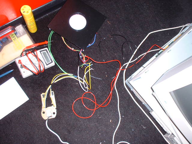
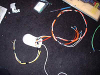
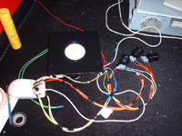
Plug the mouse into your PC, power on and boot Windows (or something which uses a mouse). (SEE PHOTO, note I'd
just twisted the wires together at this point, before I added the blade connectors). Check that the trackball works
correctly. It may be that one or both directions are the wrong way around (eg move left and cursor goes right). If this
is the case then change the wires for that axis around (probably a good idea to turn the PC off first). Note that if your left/right and up/down are the wrong way round, then you've got your X and Y Axis the wrong way round - swap the Yellow/Green for the Purple/Blue wires & vice versa.

Step 5:
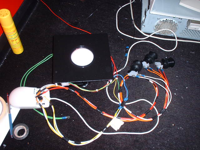
That's all the hard work done. I decided at this point to wire up some buttons to the mouse board too...
All you need to do is solder wires onto the mouse board where the tiny microswitches
are soldered on. I was unable to remove the switches (I don't have a
de-soldering tool) so I had to solder straight onto the back of the board. If
the switches have three solder points, just connect wires to the two points
which have tracks leading from them on the circuit board.

Step 6:
At this point I attempted to re-fit the mouse board back into the mouse case,
just to keep things tidy. I removed the buttons, and I had to remove a couple of
moulded protrusions from inside but it fitted back together quite nicely.
Finally, I just connected some buttons from
Ultimarc
up to the wires from the mouse buttons using blade connectors, and tidied all
the cabling up (cable ties would have been preferred to insulation tape!)
It works great! 
(last edited on 14/01/05)
|