This is a bit of a side note, there's no LCD included with the Arduino starter pack, but I figure its a popular request, so here we go!
This tutorial will soon be rewritten for the updated LiquidCrystal library. Check this tutorial page which is much more recent
 |
Assembled Arduino board, preferrably a Diecimila (or whatever the latest version is) but NG is OK too |
$35 |
 |
USB Cable. Standard A-B cable is required. Any length is OK. |
Or any computer supply store $5 |
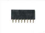 |
2 pieces of 7-pin female header (you can always cut down longer header) |
Any electronics supply store $3 |
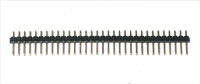 |
2 pieces of 7-pin male header (you can always cut down longer header). | Any electronics supply store $0.50 |
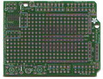 |
Arduino Prototyping Shield kit, without breadboard! |
Adafruit |
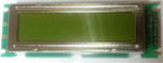 |
Character LCD with parallel interface | Pretty much any online electronics shop! |
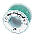 |
Hookup Wire Make sure its not stranded wire! |
Any hardware store |
The first step is to get the LCD you want. Parallel LCDs come in a couple different sizes, from 16 characters, 1 line (16x1) to 24 characters, 4 lines (24x4).

In this tutorial I use the 16x2 Picvue from Jameco because thats what was I had in my box of stuff, but you can easily adapt it for any other LCD. The wiring may differ a little bit but that will be covered.
The first step is to turn over the LCD and check out the pins. Parallel LCDs almost always have 14 or 16 pins. In this model they are all the way to the left, near the label J1. I soldered 2 7-pin female headers for e-z plugging. Somtimes the pins are along the bottom all in a row.
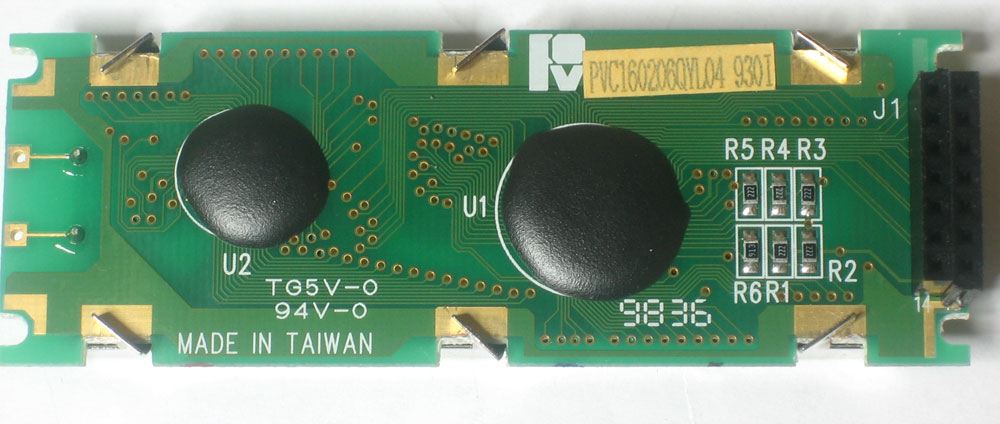
Look closely at the header for the numbers that show which pins are which. In this model, the first pin is at the top right, the second pin is top left, etc till pin 14 in the bottom left.
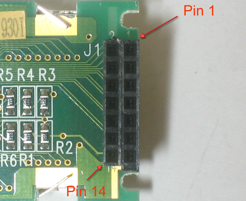
When the LCD is flipped over, the pinout will be mirrored, to help me keep track of it, I made a diagram:
1 |
2 |
|---|---|
3 |
4 |
5 |
6 |
7 |
8 |
9 |
10 |
11 |
12 |
13 |
14 |
Whatever your pinout is, make sure you have a diagram written out since you will need to refer to it many times!
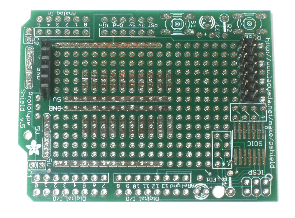
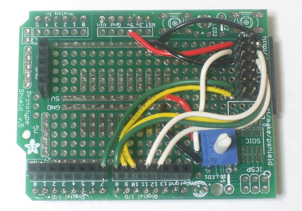
OK now that we are diagrammed out, I took the protoshield and soldered 2 7-pin headers at one end of the pcb. Note that they are not all the way to the edge, I left one row of holes so I could easily solder some wires. I also soldered a short piece of header (that comes with the shield kit) at the left so that the LCD will be propped up.
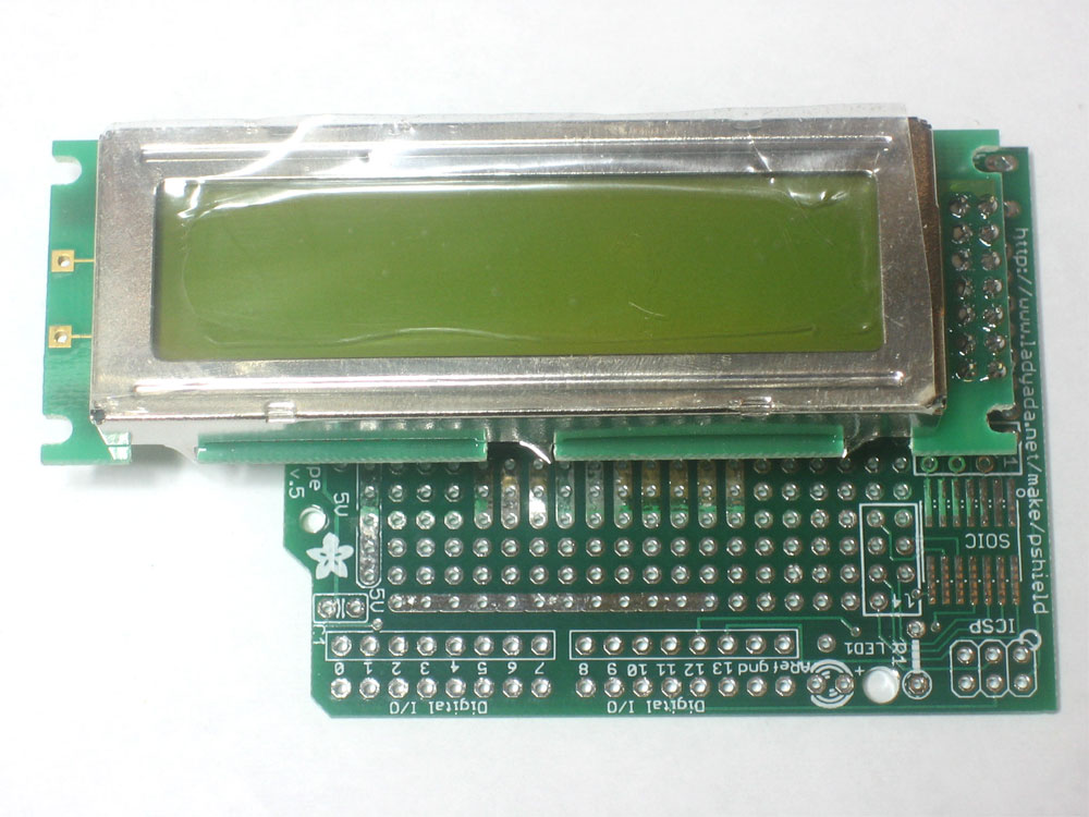
You can now do a test fit to verify how it will look. it hangs over a bit but thats OK by me
Since this is a parallel LCD, data will be sent to it over a parallel interface. That is, multiple bits at a time. These LCDs are designed for either a 8-bit or 4-bit interface. Since we'd like to save pins, lets go with the 4-bit interface! The data pins are name D4, D5, D6, and D7. Double-check your datasheet but almost all parallel LCDs have these pins numbered 4, 3, 2, and 1 respectively.
1 (D7) |
2 (D6) |
|---|---|
3 (D5) |
4 (D4) |
5 |
6 |
7 |
8 |
9 (ENABLE) |
10 (R/W) |
11 (RS) |
12 (CONTRAST) |
13 (GND/VSS) |
14 (+5V/VDD) |
There's a lot of wiring to be done but we're going to go thru it very slowly so it shouldn't be too bad.
Lets connect these to the arduino thusly: D4 -> Arduino pin #7, D5 -> Arduino pin #8, D6 -> Arduino pin #9, D4 -> Arduino pin #10
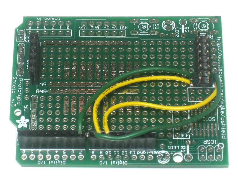
Since I wasnt sure of the wiring, I used the sockets on the protoshield. Once I test and verify they are correct, I'll solder them in!
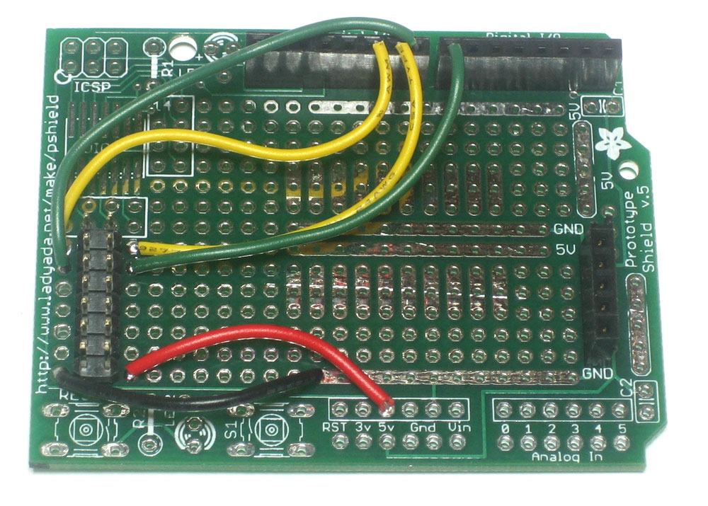
Next are the two power wires. Parallel LCDs run off of +5V so you can just solder the Vcc wire to 5V and the ground wire to GND.
Next are the 2 control wires, ENABLE and RS which we connect to pins 12 and 11 respectively.
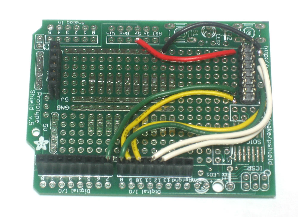
Theres another control line called R/W that you can use to control whether you're reading or writing to the LCD. Since we'll just be writing, that pin can be connected to ground, saving another arduino pin
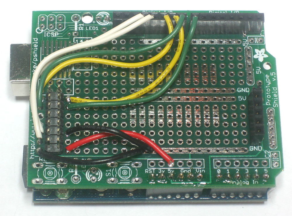
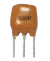
The last wire is the contrast control, we need to connect a potentiometer to this to make the display visible. I dont know the specifics of the input current but I used a 10K potentiometer and it worked great.
One pin is connected to +5V, the pin on the other side is connected to ground and the middle pin is connected to the contrast line.
Now place the LCD on top. Looks good!
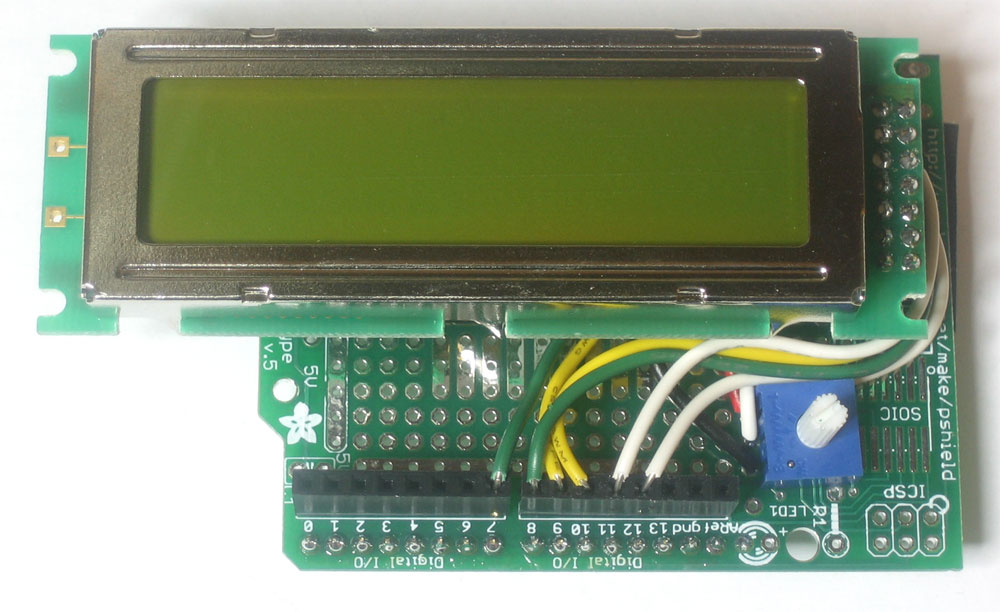
Make sure you finish up the rest of the shield so you can plug it into an arduino. At least solder in the male headers.
Our first test will be just to connect it up to power and see what happens. Plug it into an Arduino and power it up. You should see the following:
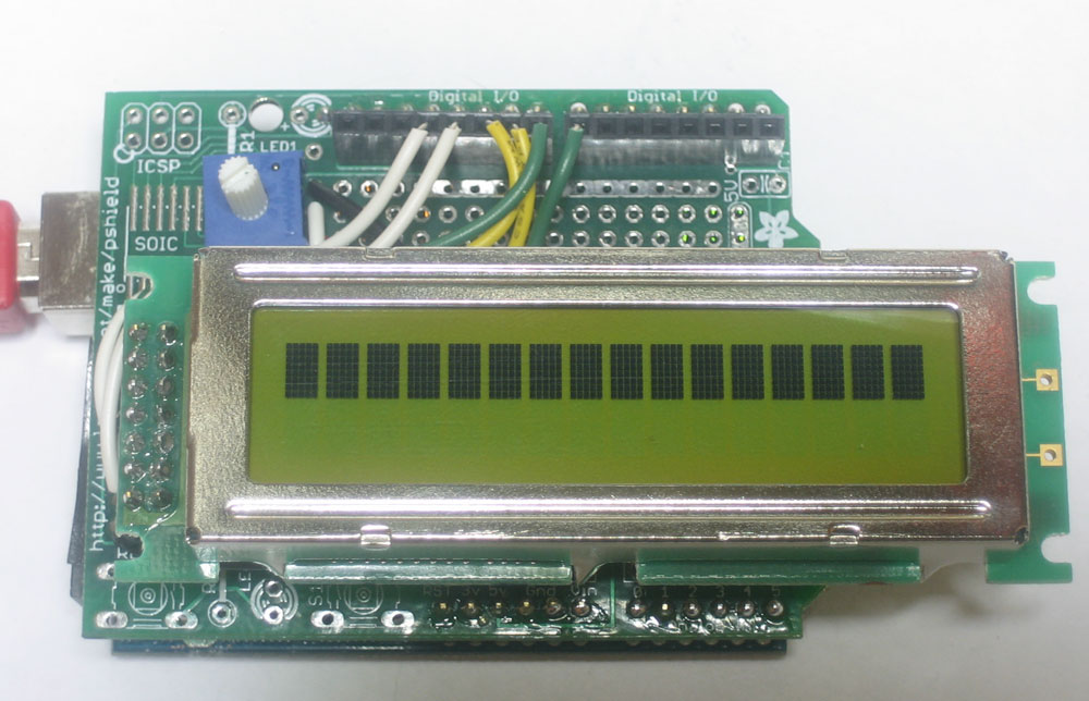
Make sure you tweak the contrast potentiometer, if the contrast is all the way down you may not see anything
Next you'll want to install the LCD4bit library, so download it from the Arduino playground
Uncompress and install the library by dragging the files into the hardware/libraries folder inside your Arduino installation
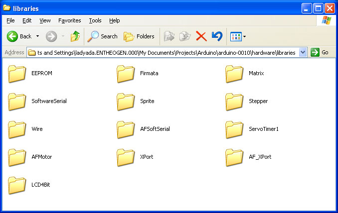
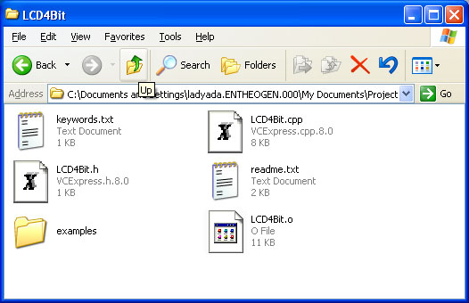
The inside of the LCD4Bit folder:
Open up LCD4Bit.cpp with a text editor such as WordPad and scroll down to the part where the pins used are defined
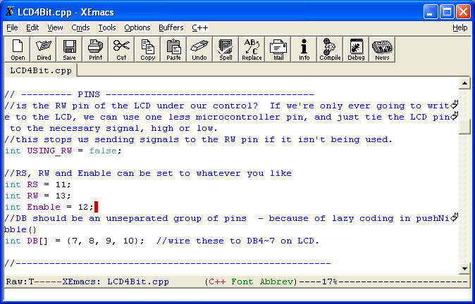
Make sure the Enable pin is set to 12 and the RS pin is 11. USING_RW should be set to false, as well.
Finally, start up your Arduino software, and select from the menu:
Sketchbook->Examples->Library-LCD4Bit->LCD4BitExample
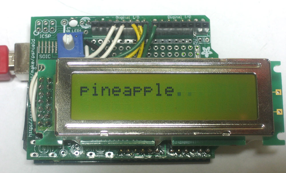
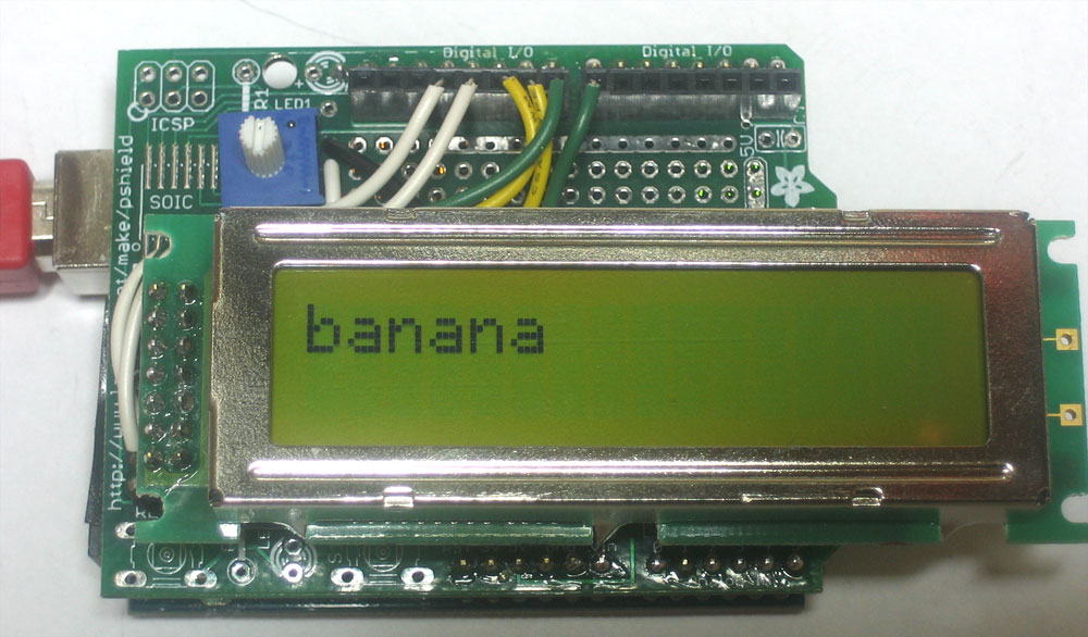
Upload the sketch to your Arduino with the LCD attached, you should see a randomized list of fruits!
Hooray! You're ready to start printing your own messages. Check out the example code to see how this is done, then just copy and paste the code into your own project.