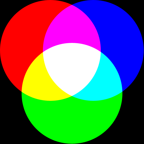
The onboard Atmex LED is red, which is all fine and everything but we want to make other nifty colors. Like fuscia and turquoise and orangeyellow. There's no such thing as a fuscia LED, so instead we will take 3 LEDs (red, green & blue) and power them at different brightness to combine into a virtual rainbow. A lot of people are familiar with the "additive color wheel" diagram[1]: Red plus green is yellow. Red plus purple is magenta (purplish). Green plus blue is cyan (light bluish). Add them together and you make white.
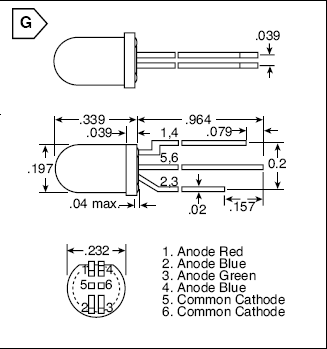
Whats neat about the RGB LED is that the three different chunks of semiconductor are in one small plastic package. In order to wire up the LED properly, we need to look at the datasheet, like we did for the plain red LED. Only problem is, there doesn't seem to be one (well let me know if you find one for it, but I couldn't). There is some information in the mouser catalog, so lets read that.
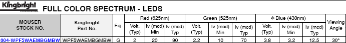
Despite lacking a datasheet, pretty much all the data necesary is here. The forward voltages (Vf) of red, green and blue: 2V, 2.2V and 3.8V. The brightness, 90mcd, 70mcd and 12.5mcd. Note that there are 2 blue LEDs, probably to make up for the fact that each one is pretty dim.
The "cathode" of an LED is the part that always gets connected to ground (or is closest to ground): current in a diode wants to flow from the "anode" to the "cathode." One way to remember that is that, alphabetically, anode comes before cathode. The reason its called a "common cathode" is that all the LEDs are connected together to the two cathode pins. Its not really clear why there are two cathode pins, probably just easier to manufacture.
Lets calculate the resistor values we want for each LED. Say we want 10mA through each LED. That means that for the red LED, (5-2)V/0.01A = 300 ohms. For the green, (5 - 2.2)/0.01 = 280 ohms. Blue, (5 - 3.8)/0.01 = 120 ohms. Lets just say that 280 = 300, its pretty close anyways. OK we're ready to wire it up!
To start, lets use a solderless breadboard (the white slab thing) to wire up the LED. You don't have to breadboard the LED, its a rather simple circuit. But its also pretty common to screw things up (in general) and with a solderless breadboard, screwing up is easy to fix whereas if you solder the LED directly, before you know 100% that you're doing it right, well its a real pain to desolder and fix that sort of thing.
To start, clip the leads so they're all the same length, this just makes it to work with. Now bend the four anode leads so that are seperated like so.
And plug it into the breadboard so that you use up five rows.
Now clip and bend the two 300ohm and two 120ohm resistors and use them to bridge the two columns.
Now connect the cathodes to ground, and the green LED's resistor to port B2, the red one's to B3 and the two blue ones to B4.
If you want to test/play with the RGB led, take the wires that connect from the resistor to the port and try plugging them directly into 5V to light them up.
OK lets write some basic code to color mix:
00001 // this is the header file that tells the compiler what pins and ports, etc.
00002 // are available on this chip.
00003 #include <avr/io.h>
00004
00005 // define what pins the LEDs are connected to.
00006 // in reality, PB2/PB3/PB4 are also constants. e.g PB2 is 2
00007 #define GREEN PB2
00008 #define RED PB3
00009 #define BLUE PB4
00010
00011 // Some macros that make the code more readable
00012 #define output_low(port,pin) port &= ~(1<<pin)
00013 #define output_high(port,pin) port |= (1<<pin)
00014 #define set_input(portdir,pin) portdir &= ~(1<<pin)
00015 #define set_output(portdir,pin) portdir |= (1<<pin)
00016
00017 int main(void) {
00018   // initialize the direction of the B port to be outputs
00019   // on the 3 pins that have LEDs connected
00020   set_output(DDRB, RED);
00021   set_output(DDRB, GREEN);
00022   set_output(DDRB, BLUE);
00023
00024   // turn on RED and BLUE to make...magenta (purple)!
00025   output_high(PORTB, RED);
00026   output_low(PORTB, GREEN);
00027   output_high(PORTB, BLUE);
00028
00029   return 0;
00030 }
This is pretty much just like the ledblink.c code, except we're not blinking and we're using different pins. Compile and upload it as before. Pretty simple. You can go through and experiment with mixing in different ways to make all 7 colors in the colorwheel. You'll note that the colors aren't exactly what they ought to be (particularly white)...this LED isn't really perfectly calibrated.
Now we go back & combine ledblink.c and the basic colormixing code to make a blinking colormix
00001 // this is the header file that tells the compiler what pins and ports, etc.
00002 // are available on this chip.
00003 #include <avr/io.h>
00004
00005 // define what pins the LEDs are connected to.
00006 // in reality, PB2/PB3/PB4 are also constants. e.g PB2 is 2
00007 #define GREEN PB2
00008 #define RED PB3
00009 #define BLUE PB4
00010
00011 // Some macros that make the code more readable
00012 #define output_low(port,pin) port &= ~(1<<pin)
00013 #define output_high(port,pin) port |= (1<<pin)
00014 #define set_input(portdir,pin) portdir &= ~(1<<pin)
00015 #define set_output(portdir,pin) portdir |= (1<<pin)
00016
00017 // this is just a program that 'kills time' in a calibrated method
00018 void delay_ms(uint8_t ms)
00019 {
00020   uint16_t delay_count = F_CPU / 17500;
00021   volatile uint16_t i;
00022
00023   while (ms != 0) {
00024     for (i=0; i != delay_count; i++);
00025     ms--;
00026   }
00027 }
00028
00029
00030 int main(void) {
00031   // initialize the direction of the B port to be outputs
00032   // on the 3 pins that have LEDs connected
00033   set_output(DDRB, RED);
00034   set_output(DDRB, GREEN);
00035   set_output(DDRB, BLUE);
00036
00037   while (1) {
00038     // start with all the LEDs off
00039     output_low(PORTB, RED);
00040     output_low(PORTB, GREEN);
00041     output_low(PORTB, BLUE);
00042
00043     // turn on the red light for 200ms
00044     output_high(PORTB, RED);
00045     delay_ms(200);
00046
00047     // turn on red & green -> yellow for 200ms
00048     output_high(PORTB, GREEN);
00049     delay_ms(200);
00050
00051     // now turn off red to make just green
00052     output_low(PORTB, RED);
00053     delay_ms(200);
00054
00055     // now turn on green & blue to make greenish-blue
00056     output_high(PORTB, BLUE);
00057     delay_ms(200);
00058
00059     // turn off green -> blue
00060     output_low(PORTB, GREEN);
00061     delay_ms(200);
00062
00063     // turn on red again to make purple
00064     output_high(PORTB, RED);
00065     delay_ms(200);
00066
00067     // now start over
00068   }
00069 }
- Change the blinking color mix code to blink out a customized set of colors and speeds (ie green, blue, white & turquoise)