Before we go crazy with LEDs, its time for some boring review. This stuff isnt really necessary, you can always use an online "LED calculator," but its still handy to read over.
LED stands for "Light Emitting Diode" and, well, thats a really good description. The "light emitting" part is pretty obvious: its a piece of electronics encased in a translucent plastic casing and when electricity is passed through it, light comes out. What's the "diode" part mean? Well, basically, "diode" is what electrical engineers call a "PN junction" which basically just means that two differing chunks of semiconductor (P-type and N-type) are stuck together. Where they meet is the "junction." Basically this isn't very important but if anyone refers to that sort of junction its probably the same as a diode.
Diodes have 2 important properties. One is that electricity only passes one way through it. If you try to pass electricity the other way, its like petting a cat the wrong way and the cat gets angry and bites you. Except what really happens is that the diode starts getting unhappy and eventually dies. (Sometimes it releases "magic smoke" to let you know). Another thing to note is not only can you only put current and voltage (power) in one way. Theres also two properties called the "forward current" and "forward voltage" that dictates just how much current/voltage (power) the diode likes to handle.
So clearly these are some pretty valuable things to understand about your LED before you go and use it without damaging it. Although there are some guidelines that people use, it never hurts to go to the source and read the datasheet. For example here is the datasheet for the red LED used on the Atmex board.
Reading a datasheet is a pretty important skill. You have to figure out what data you want and where it is. This one is pretty simple.
- First thing you see is "Peak Forward Current" (30mA) this tells you how much current the LED is comfortable passing. The more current, the more light. So its a tradeoff between power consumption and brightness.
- Second thing is the "Reverse Voltage" (5V) this tells you how much voltage you can put on the LED backwards before it dies. You shouldn't really be putting it in backwards but just so you know, thats how much it can take before damage occurs
- Next is "Luminous Intesnsity" which is basically, how bright is it? According to the datasheet its usually ~9 millicandella (mcd). Thats pretty dim, but since the LED is really just a small indicator, not a flashlight, its OK. It also says how much current went through the LED to make this measurement (10mA, a third of the maximum).
- The last really important value is the "Forward Voltage, Vf" which is what voltage the diode likes to be at. For almost all red LEDs, its somewhere around 2.2 volts.
- Theres other handy data in the datasheet, like whats the color (wavelength) and what is the angle of light spread, etc. etc
So on the last page there are some handy graphs. For example, this one:
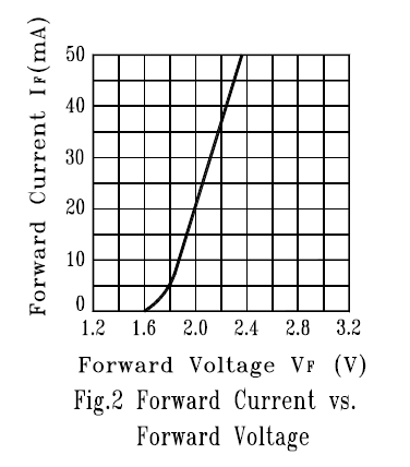
So whats happening here? Basically this graph shows you the relationship between the voltage you put across the LED to the current that goes through it. Clearly the more voltage you put across, the more current goes through. Well, say you put 5V across the LED...if so then the current would be at least 100mA, maybe more. The graph doesn't even show it because you're not supposed to put more than 30mA through before the LED starts burning up. Note also that a small change in voltage (say, between 2.0V and 2.2V a 10% increase) makes a big change in the current (20mA to 35mA, more than 100%)! Another thing to remember here is that this graph isn't 100% guaranteed: it could be that 2.1V causes 20mA to pass through, or maybe 1.9V.
This is a problem, because that means we'd have to test every single LED we want to use to find the precise version of the graph above to find exactly what voltage to put across it so that 20mA goes through it, before we use it in a circuit. Obviously, we don't want to do that. So we make an engineering approximation.
First, we make an assumption about the Vf, we'll say its 2.0V (the 'typical' Vf from the datasheet) and we'll assume that it never gets any higher or lower than that. Next we get a voltage source thats at least a volt higher. Lucky for us, the Atmex board has a nice 5 volt supply ready. Then we put a resistor between the power and the LED like so:
(image)
Since the voltage across the LED is assumed to be 2.0V then the voltage across the resistor must 3.0V (since the voltages must add up to 5V). We already know that resistors have the rule V = IR, and V = 3.0. I is the current through the resistor, and theres nowhere else for that current to go to reach ground, so it must go through the LED. We already said we want 20mA through the LED. That means I = .020. That leaves us with R = V / I = 3.0 / .02 = 150 ohms.
Lets go back and verify that this design is a good one. If R = 150 and say Vf is not 2.0 but really 2.2, then V = 2.8 and I = V/R = 2.8/150 = 19mA. If Vf is really 1.8, likewise I = 21mA. Now a 10% change in Vf corresponds to a 5% change in the current, not 100% like before. Great!
So if you ever find yourself needing to hook up an LED without the datasheet here are some rules of thumb: 20mA is good for the forward current, red/orange/amber/yellow LEDs have a Vf around 2.1V, green/blue/violet/white LEDs have a Vf of 3.4V, each LED should have its own resistor, and a volt or more of 'headroom' (voltage across the resistors) is nice.