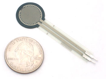
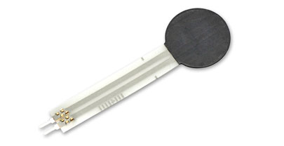
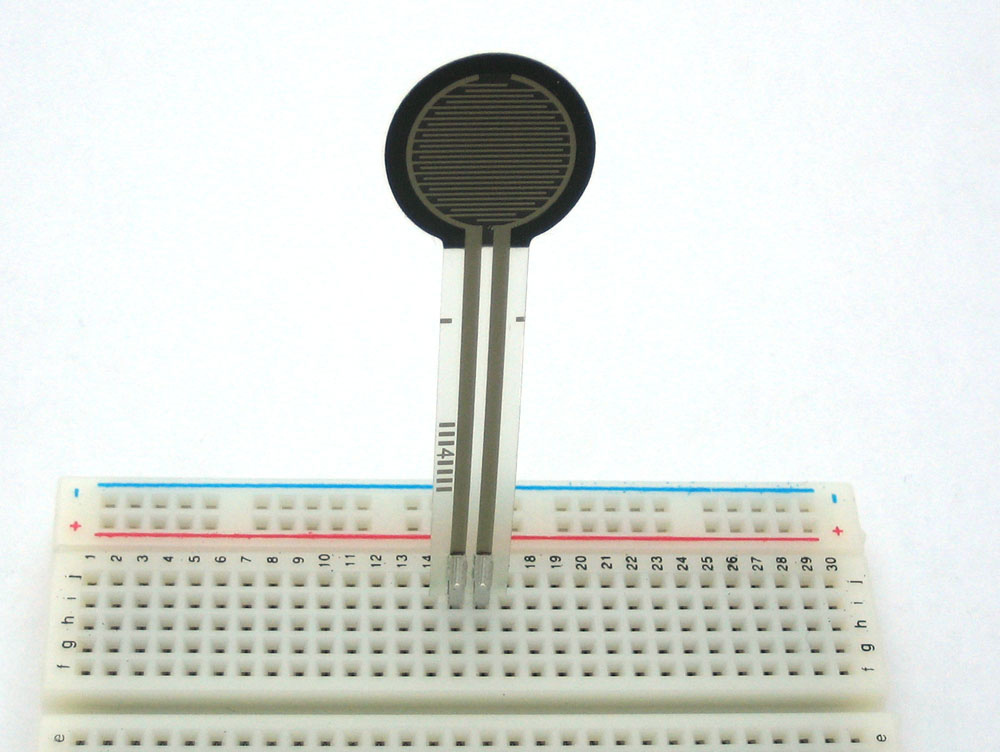
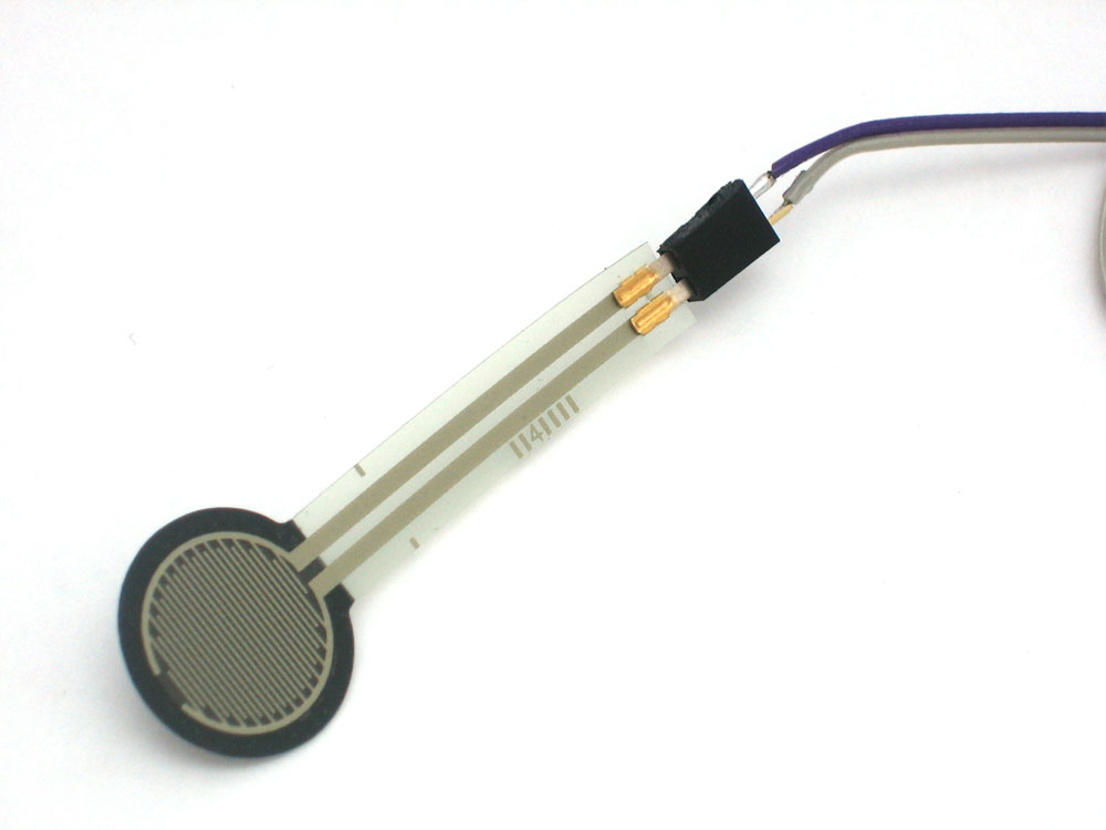
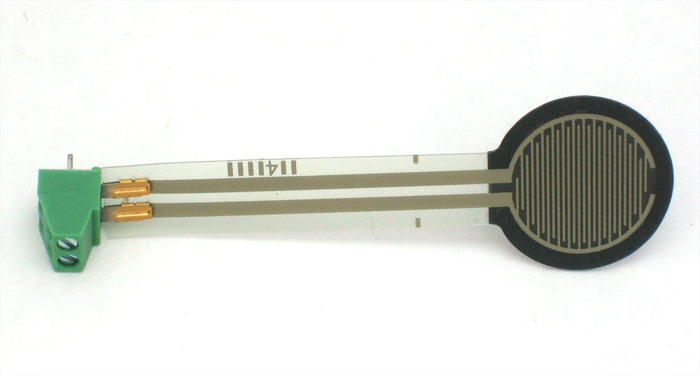
This is a photo of an FSR, specifically the Interlink 402 model. The 1/2" diameter round part is the sensitive bit
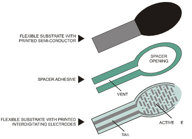
The FSR is made of 2 layers seperated by a spacer. The more one presses, the more of those Active Element dots touch the semiconductor and that makes the resistance go down
FSRs are sensors that allow you to detect physical pressure, squeezing and weight. They are simple to use and low cost.
FSR's are basically a resistor that changes its resistive value (in ohms Ω) depending on how much its pressed. These sensors are fairly low cost, and easy to use but they're rarely accurate. They also vary some from sensor to sensor perhaps 10%. So basically when you use FSR's you should only expect to get ranges of response. While FSRs can detect weight, they're a bad choice for detecting exactly how many pounds of weight are on them.
However, for most touch-sensitive applications like "has this been squeezed or pushed and about how much" they're a good deal for the money!
- Size: 1/2" (12.5mm) diameter active area by 0.02" thick (Interlink does have some that are as large as 1.5"x1.5")
- Price $7.00 from the Adafruit shop
- Resistance range: Infinite/open circuit (no pressure), 100KΩ (light pressure) to 200Ω (max. pressure)
- Force range: 0 to 20 lb. (0 to 100 Newtons) applied evenly over the 0.125 sq in surface area
- Power supply: Any! Uses less than 1mA of current (depends on any pullup/down resistors used and supply voltage)
- Datasheet (note there are some mathematical inconsistancies in here)
As we've said, the FSR's resistance changes as more pressure is applied. When there is no pressure, the sensor looks like an infinite resistor (open circuit), as the pressure increases, the resistance goes down. This graph indicates approximately the resistance of the sensor at different force measurements. (Note that force is not measured in grams and what they really mean is Newtons * 100!)
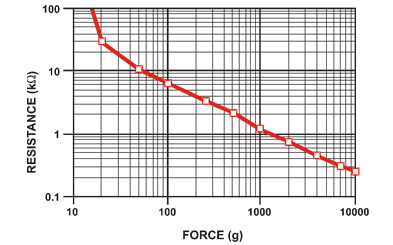
Its important to notice that the graph isn't really linear (its a log/log graph) and that at especially low force measurements it quickly goes from infinite to 100KΩ
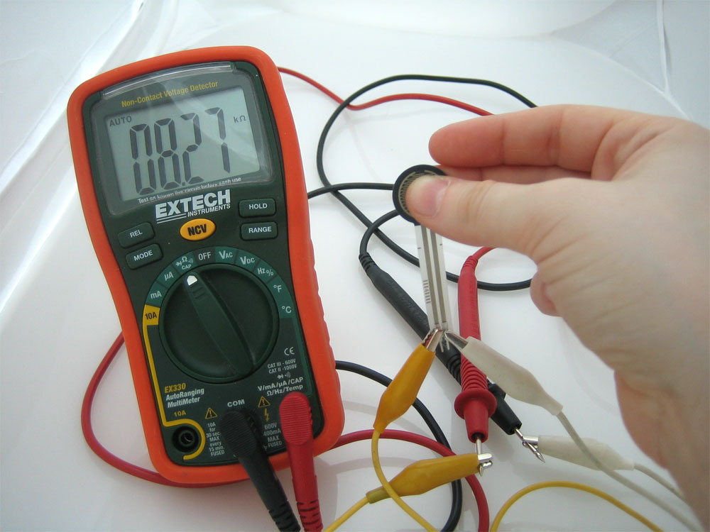
The easiest way to determine how your FSR works is to connect a multimeter in resistance-measurement mode to the two tabs on your sensor and see how the resistance changes. Because the resistance changes a lot, a auto-ranging meter works well here. Otherwise, just make sure you try different ranges, between 1MΩ and 100Ω before 'giving up'.
Because FSRs are basically resistors, they are non-polarized. That means you can connect them up 'either way'a and they'll work just fine!
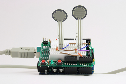
FSRs are often a polymer with conductive material silk-screened on. That means they're plastic and the connection tab is crimped on somewhat delicate material. The best way to connect to these is to simply plug them into a breadboard
or use a clamp-style connector like alligator clips (see above), female header
or a terminal block such as Phoenix #1881448
It is possible to solder onto the tabs but you must be very fast because if your iron is not good quality or you dally even a few seconds, you will melt the plastic and ruin the FSR! Don't attempt to solder directly to your FSR unless you are absolutely sure you have the skills to do so.
Here are just a few examples of projects that use FSRs!
Interfacing with Flash (or Processing would work well too!) to change the screen display
Control LEDs (its a little dark but he's pressing an FSR)
FSR thumb-wrestling (example from Stanford U. class)
Tapper, a musical interface that works by having you tap your fingers to the music
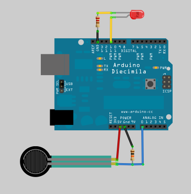
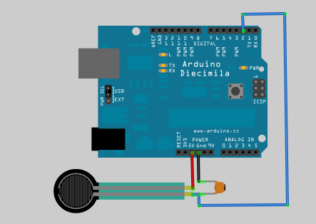
The easiest way to measure a resistive sensor is to connect one end to Power and the other to a pull-down resistor to ground. Then the point between the fixed pulldown resistor and the variable FSR resistor is connected to the analog input of a microcontroller such as an Arduino (shown)
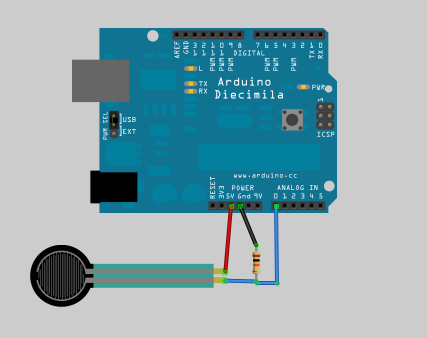
For this example I'm showing it with a 5V supply but note that you can use this with a 3.3v supply just as easily. In this configuration the analog voltage reading ranges from 0V (ground) to about 5V (or about the same as the power supply voltage).
The way this works is that as the resistance of the FSR decreases, the total resistance of the FSR and the pulldown resistor decreases from about 100Kohm to 10Kohm. That means that the current flowing through both resistors increases which in turn causes the voltage across the fixed 10K resistor to increase. Its quite a trick!
| Force (lb) | Force (N) | FSR Resistance | (FSR + R) Ω |
Current thru FSR+R | Voltage across R |
|---|---|---|---|---|---|
| None | None | Infinite |
Infinite! |
0 mA |
0V |
| 0.04 lb | 0.2 N | 30KΩ |
40 KΩ |
0.13 mA |
1.3 V |
| 0.22 lb | 1 N | 6 KΩ |
16 KΩ |
0.31 mA |
3.1 V |
| 2.2 lb | 10 N | 1 KΩ |
11 KΩ |
0.45 mA |
4.5 V |
| 22 lb | 100 N | 250 Ω |
10.25 KΩ |
0.49 mA |
4.9 V |
Note that our method takes the somewhat linear resistivity but does not provide linear voltage! That's because the voltage equasion is:
Vo = Vcc ( R / (R + FSR) )
That is, the voltage is proportional to the inverse of the FSR resistance.
This sketch will take the analog voltage reading and use that to determine how bright the red LED is. The harder you press on the FSR, the brighter the LED will be! Remember that the LED has to be connected to a PWM pin for this to work, I use pin 11 in this example.
These examples assume you know some basic Arduino programming. If you don't, maybe spend some time reviewing the basics at the Arduino tutorial?
/* FSR testing sketch.

Connect one end of FSR to 5V, the other end to Analog 0.
Then connect one end of a 10K resistor from Analog 0 to ground
Connect LED from pin 11 through a resistor to ground

For more information see www.ladyada.net/learn/sensors/fsr.html */

int fsrAnalogPin = 0; // FSR is connected to analog 0
int LEDpin = 11;      // connect Red LED to pin 11 (PWM pin)
int fsrReading;      // the analog reading from the FSR resistor divider
int LEDbrightness;

void setup(void) {
  Serial.begin(9600);   // We'll send debugging information via the Serial monitor
  pinMode(LEDpin, OUTPUT);
}

void loop(void) {
  fsrReading = analogRead(fsrAnalogPin);
  Serial.print("Analog reading = ");
  Serial.println(fsrReading);

  // we'll need to change the range from the analog reading (0-1023) down to the range
  // used by analogWrite (0-255) with map!
  LEDbrightness = map(fsrReading, 0, 1023, 0, 255);
  // LED gets brighter the harder you press
  analogWrite(LEDpin, LEDbrightness);

  delay(100);
}
This code doesn't do any calculations, it just prints out what it interprets as the amount of pressure in a qualitative manner. For most projects, this is pretty much all thats needed!
 /* FSR simple testing sketch.

Connect one end of FSR to power, the other end to Analog 0.
Then connect one end of a 10K resistor from Analog 0 to ground

For more information see www.ladyada.net/learn/sensors/fsr.html */

int fsrPin = 0;     // the FSR and 10K pulldown are connected to a0
int fsrReading;     // the analog reading from the FSR resistor divider

void setup(void) {
  // We'll send debugging information via the Serial monitor
  Serial.begin(9600);
}

void loop(void) {
  fsrReading = analogRead(0);

  Serial.print("Analog reading = ");
  Serial.print(fsrReading);     // the raw analog reading

  // We'll have a few threshholds, qualitatively determined
  if (fsrReading < 10) {
    Serial.println(" - No pressure");
  } else if (fsrReading < 200) {
    Serial.println(" - Light touch");
  } else if (fsrReading < 500) {
    Serial.println(" - Light squeeze");
  } else if (fsrReading < 800) {
    Serial.println(" - Medium squeeze");
  } else {
    Serial.println(" - Big squeeze");
  }
  delay(1000);
}
This Arduino sketch that assumes you have the FSR wired up as above, with a 10KΩ pull down resistor and the sensor is read on Analog 0 pin. It is pretty advanced and will measure the approximate Newton force measured by the FSR. This can be pretty useful for calibrating what forces you think the FSR will experience
/* FSR testing sketch.

Connect one end of FSR to power, the other end to Analog 0.
Then connect one end of a 10K resistor from Analog 0 to ground

For more information see www.ladyada.net/learn/sensors/fsr.html */

int fsrPin = 0;     // the FSR and 10K pulldown are connected to a0
int fsrReading;     // the analog reading from the FSR resistor divider
int fsrVoltage;     // the analog reading converted to voltage
unsigned long fsrResistance;  // The voltage converted to resistance, can be very big so make "long"
unsigned long fsrConductance;
long fsrForce;       // Finally, the resistance converted to force

void setup(void) {
  Serial.begin(9600);   // We'll send debugging information via the Serial monitor
}

void loop(void) {
  fsrReading = analogRead(fsrPin);
  Serial.print("Analog reading = ");
  Serial.println(fsrReading);

  // analog voltage reading ranges from about 0 to 1023 which maps to 0V to 5V (= 5000mV)
  fsrVoltage = map(fsrReading, 0, 1023, 0, 5000);
  Serial.print("Voltage reading in mV = ");
  Serial.println(fsrVoltage);

  if (fsrVoltage == 0) {
    Serial.println("No pressure");
  } else {
    // The voltage = Vcc * R / (R + FSR) where R = 10K and Vcc = 5V
    // so FSR = ((Vcc - V) * R) / V        yay math!
    fsrResistance = 5000 - fsrVoltage;     // fsrVoltage is in millivolts so 5V = 5000mV
    fsrResistance *= 10000;                // 10K resistor
    fsrResistance /= fsrVoltage;
    Serial.print("FSR resistance in ohms = ");
    Serial.println(fsrResistance);

    fsrConductance = 1000000;           // we measure in micromhos so
    fsrConductance /= fsrResistance;
    Serial.print("Conductance in microMhos: ");
    Serial.println(fsrConductance);

    // Use the two FSR guide graphs to approximate the force
    if (fsrConductance <= 1000) {
      fsrForce = fsrConductance / 80;
      Serial.print("Force in Newtons: ");
      Serial.println(fsrForce);
    } else {
      fsrForce = fsrConductance - 1000;
      fsrForce /= 30;
      Serial.print("Force in Newtons: ");
      Serial.println(fsrForce);
    }
  }
  Serial.println("--------------------");
  delay(1000);
}
Because FSR's are basically resistors, its possible to use them even if you don't have any analog pins on your microcontroller (or if say you want to connect more than you have analog input pins. The way we do this is by taking advantage of a basic electronic property of resistors and capacitors. It turns out that if you take a capacitor that is initially storing no voltage, and then connect it to power through a resistor, it will charge up to the power voltage slowly. The bigger the resistor, the slower it is.
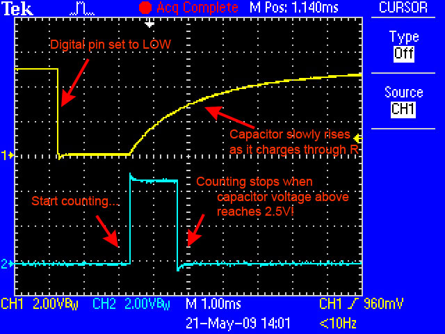
This capture from an oscilloscope shows whats happening on the digital pin (yellow). The blue line indicates when the sketch starts counting and when the couting is complete, about 1.2ms later.
This is because the capacitor acts like a bucket and the resistor is like a thin pipe. To fill a bucket up with a very thin pipe takes enough time that you can figure out how wide the pipe is by timing how long it takes to fill the bucket up halfway.
In this case, our 'bucket' is a 0.1uF ceramic capacitor. You can change the capacitor nearly any way you want but the timing values will also change. 0.1uF seems to be an OK place to start for these FSRs.
/* FSR simple testing sketch.

Connect one end of FSR to power, the other end to pin 2.
Then connect one end of a 0.1uF capacitor from pin 2 to ground

For more information see www.ladyada.net/learn/sensors/fsr.html */

int fsrPin = 2;     // the FSR and cap are connected to pin2
int fsrReading;     // the digital reading
int ledPin = 13;    // you can just use the 'built in' LED

void setup(void) {
  // We'll send debugging information via the Serial monitor
  Serial.begin(9600);
  pinMode(ledPin, OUTPUT);  // have an LED for output
}

void loop(void) {
  // read the resistor using the RCtime technique
  fsrReading = RCtime(fsrPin);

  if (fsrReading == 30000) {
    // if we got 30000 that means we 'timed out'
    Serial.println("Nothing connected!");
  } else {
    Serial.print("RCtime reading = ");
    Serial.println(fsrReading);     // the raw analog reading

    // Do a little processing to keep the LED blinking
    fsrReading /= 10;
    // The more you press, the faster it blinks!
    digitalWrite(ledPin, HIGH);
    delay(fsrReading);
    digitalWrite(ledPin, LOW);
    delay(fsrReading);
  }
  delay(100);
}

// Uses a digital pin to measure a resistor (like an FSR or photocell!)
// We do this by having the resistor feed current into a capacitor and
// counting how long it takes to get to Vcc/2 (for most arduinos, thats 2.5V)
int RCtime(int RCpin) {
 int reading = 0;  // start with 0

  // set the pin to an output and pull to LOW (ground)
  pinMode(RCpin, OUTPUT);
  digitalWrite(RCpin, LOW);

  // Now set the pin to an input and...
  pinMode(RCpin, INPUT);
  while (digitalRead(RCpin) == LOW) { // count how long it takes to rise up to HIGH
    reading++;      // increment to keep track of time

    if (reading == 30000) {
      // if we got this far, the resistance is so high
      // its likely that nothing is connected!
      break;           // leave the loop
    }
  }
  // OK either we maxed out at 30000 or hopefully got a reading, return the count

  return reading;
}
It is possible to calculate the actual resistance from the reading but unfortunately, variations in the IDE and arduino board will make it inconsistant. Be aware of that if you change IDE versions of OS's, or use a 3.3V arduino instead of 5V, or change from a 16mhz Arduino to a 8Mhz one (like a lilypad) there may be differences due to how long it takes to read the value of a pin. Usually that isn't a big deal but it can make your project hard to debug if you aren't expecting it!