GENERAL CONSTRUCTION GENERAL CONSTRUCTION
Once I had finalized my digital design, I transferred
the measurements from the 3D model to the wood, and began cutting the side panels for the
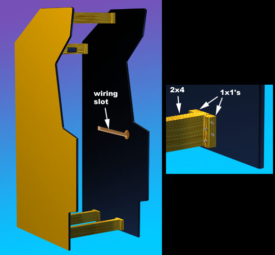
cabinet using a router. To provide for the axle of my rotating control panel, I
drilled a 2" hole thru both panels, then routed a slot into the right side panel,
that the wiring would later pass thru. After sanding the edges and rounding the
corners, I laminated the panels with yellow
Wilsonart laminate (D341-60 Marigold) and installed the t-molding on the edges, to prevent
damage to the corners.
To prepare for connecting the side
panels together, 3" sections of 1x1 were glued with polyurethane glue and screwed
into pre-drilled holes in the panels, then cross-screwed into the four 25 1/4" 2x4's
that form the frame of the cabinet. #8 x 1 1/2" screws were used.
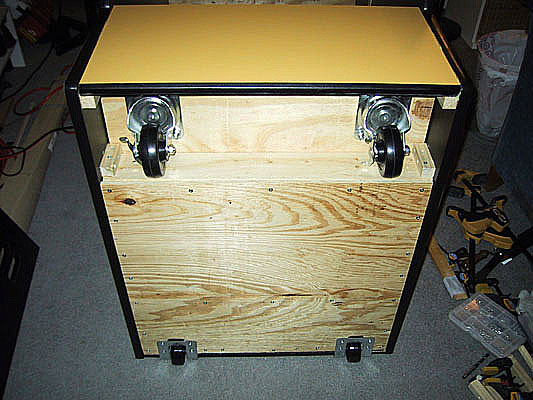
Next day, after the glue had set, I assembled the base
of the cabinet, which consists of 2 plywood sheets screwed into the bottom set of 2x4's,
one sheet above (forming the floor of the cabinet) and the other (shorter) sheet
below. This left enough room for the front swivel casters to turn. The
front and rear kick-plates and casters were then installed.
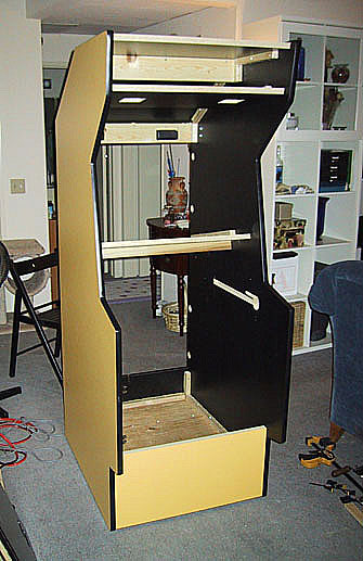
At this point, all the various panels could be joined
to the cabinet, starting with the monitor shelf to give a bit more strength. All
panels were joined to the cab by first marking the side panels, then glueing and screwing
1x1's to the sides, and then gluing and screwing the smaller panels to the 1x1's. (I
used over 300 screws in the construction of the cab!)
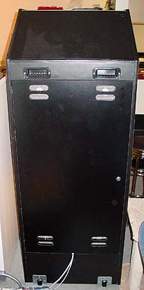
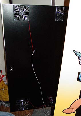
I added the back door by carefully
hanging it from the two holes cut for the cabinet "dolly" handles,
using clamps to suspend and level it out. Four hidden hardware cabinet
hinges were screwed in from the inside of the cab. Once the door was
secure, I added four 5" PC case fans to the inside, complete with
screens to minimize dust inside the cab. I ended up only connecting
the two fans near the outside edge of the door, as four fans proved to be
too noisy. The two remaining fans are more than enough blow out all
the hot air, with cool air being sucked in thru the unused fan
openings. The fans draw power from the PC's 12V power source.
Note the slot cut into the back kickplate, which allows several cables to
run out the cab (for power, networking etc.)
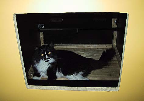
As soon as I put the front access door
on, I found an unexpected visitor had taken up residence... I just
turned around, and there he was! This guy was always waiting to steal
a bolt, climb up on the monitor shelf, or get a taste of the polyurethane
glue! Daddy's little helper indeed...
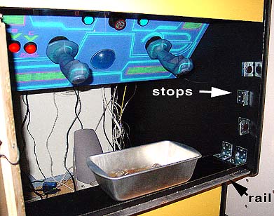
I added the coin door, using four
carriage bolts, and a bread pan for a coin box
(hey, it worked for Pong!) In order to keep the doors from pushing
too far into the cab, I fashioned some stops from some spare
L-brackets. Adhesive felt pieces were added to protect the doors and
allow them to close quietly. An additional bracket was added as a
latch for the door locks to grab onto. At this time I also
discovered it was necessary to add a metal rail along the bottom egde of
the coin box shelf. This keeps the somewhat long/skinny front access
door from being pushed downward by the control panel when everything is
closed up.
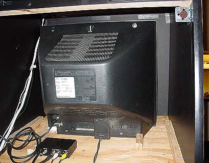
After buying all the controls, building
materials, tools, and printed artwork, the money finally ran out for this
project. The cabinet was originally designed around the 27" Wells
Gardner D9200 VGA arcade monitor, but I ended up putting off that purchase
temporarily. So for now, I just have to make do with my old Panasonic
21" TV. An RF modulator converts the GeForce's composite signal
for the TV, which only accepts a coax connection. It's not the
greatest picture, but with the sharpness and brightness cranked all the way
up, it looks decent! A couple of wood blocks hold the TV in place, so
it doesn't slide when the cab is being moved.
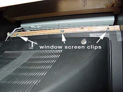
I've made a temporary monitor bezel of
black foamcore, held in place by friction with the sides of the cab.
This will eventually be replaced by one of Happ's 27" bezels when I
replace the monitor. The monitor glass (actually 1/4" Lexan) is
held in place by a set of three window screen clips, screwed into a length
of 1x1 pine, which is attached at the back edge of the speaker panel.
Note the marquee light, just above.
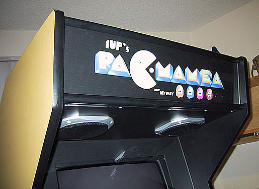
Finally, I installed the speakers & Radio Shack speaker grilles, marquee light, and a temporary marquee. I added a
Happ pushbutton on top of the cab as a remote PC power button, and soldered
a relay into a cheap power strip. The relay is wired to one of the PC's
5V power leads, so when the computer goes on, everything goes on!
(Well, everything except the TV, which has to be powered on by the remote,
thru a small hole in the bezel...) Then I quickly jammed all the
guts inside for my first MAME party!
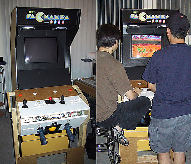
The day of the party, I still hadn't gotten the
rotating control panels built, so I hooked up the old test panels. No one seemed to mind,
though, and everyone was impressed with my machine! It ended up
playing much like a showcase cab, but with a small screen. Here are two of the 10 or so
partygoers having a blast on TMNT! We also had a PlayStation 2 running the latest
Gran Turismo 3 and Grand Theft Auto on the home theater, and lots & lots of pizza!
Thanks to all the Luma crew for coming!
DESIGN = CONSTRUCTION = ARTWORK
= HARDWARE
= SOFTWARE
= DOWNLOADS |
| The
information on this site is for the purposes of education and
entertainment only. The owner of this site makes no warantees as to
the accuracy of the information, and takes no responsibility for any
damage or injury sustained due to the use of information herein. The
design of the Pac-Mamea cabinet and all photos, computer renderings,
drawings, schematics, and printed information relating to such are
Copyright © 2002-2004 Robert Meyers. No ownership of other
copyrighted material found on this site is implied. |