|
 Rotating Control
Panels Rotating Control
Panels
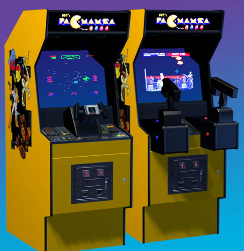
One of the key features of Pac-Mamea
is its 3-sided rotating control panel. This allows me to play many different arcade
games, using their original control setup, with a minimum interruption of play time.
During play, the 2 unused panels are hidden within the body of the cabinet, so there is no
chance of accidentally bumping the controls and interfering with gameplay. In
addition, the third panel features a modular design, with support for removable controls,
such as a Star Wars yoke, dual Terminator 2 positional guns, steering wheels, USB
gamepads, and anything else I minght need in the future. All the main controls are
connected simultaneously, so no connecting or disconnecting is necessary. Just open
the front access door, flip over the panel, and you're ready to go!
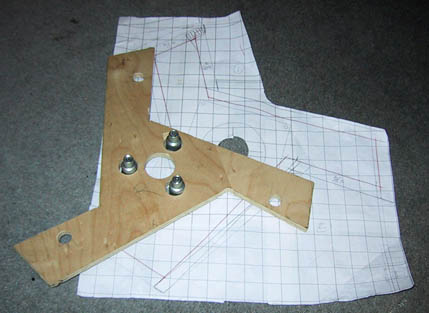
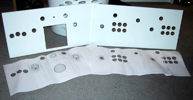
Using my CG model, I printed 1:1 plans
of my control panels and the triangular end plates. After rubbing pencil on the
backs, I taped the plans to the wood and traced over the outlines, transfering the
computer-world measurements to my panels. It was then a simple matter to drill and
cut from these measurements.
On the prototype panels (see the PROJECTS
section), I used a hitch pin on either side to hold everything in place. This is
basically what Xiaou2
did with his original rotating panels. I knew I didn't want to have Frankenstein
bolts sticking out of my final cab, and ideally, I wanted the panels to self-locate when
they were rotated into place. Finally, looking around Home Depot, I found the
answer:
Roller latches!
These are spring-loaded latches used for wardrobe doors and such. I decided I would
put 3 of these on each side, so with 6 roller latches, it should hold everything pretty
well. (In fact, they can hold the weight of the installed CPs by themselves!)
All I needed was a way for them to lock in with the sides of the cabinet. Back to
Home Depot several times, I never could come up with a simple solution (my favorite
kind!) It was finally on the night before beginning final construction that my eyes
caught something I must have passed a dozen times:
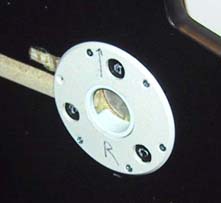
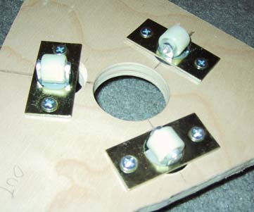
It's a 5" diameter wall protector, you know for
keeping doorknobs from bashing the walls. It was the perfect size to act as a track
for my roller latches, and it was plastic, so I didn't have to wear out my tools on a
metal plate. I drilled a 2" hole in the center thru which a PVC pipe
protrudes, forming the axle for the CP. There are three 5/8" holes drilled
equal distances from center, and 120o apart, into which the rollers can
lock. The plate also keeps the rollers from getting stuck in the 3/4" slot
routered into the inside-right of the cab, thru which the wiring from my CP passes to the
PC in the back.
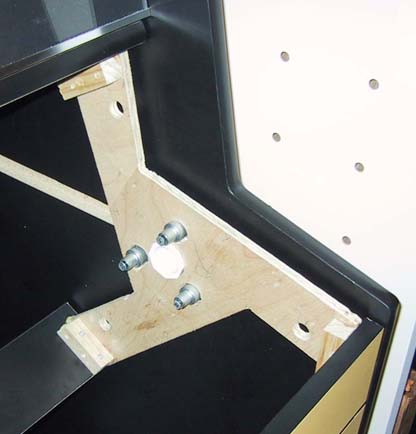
Another PVC piece is inserted thru a 1 3/4"
hole in the CP end plates, and fits somewhat tightly into the other PVC piece. I
will be adding a screw or something to keep it secure, as it tends to work its way out as
I turn the CP around.
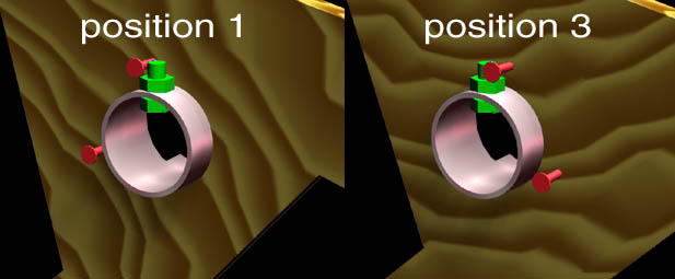
I will also be adding a bolt thru the
inner pipe, and gluing or screwing the inner pipe permanently to the outer pipe, which
in turn is glued into the 2" hole in the side panel. The rotation
would be limited by placing a screw in the end plate, in such a way that it
catches on the bolt in the PVC when it is turned past postion 1.
Another screw could be placed so that the panels can not be rotated beyond
position 3, so that the CP can't
be turned around more than 240o. So you can rotate from panel 1, to 2, to
3, but no further, so the wiring won't tangle or twist.
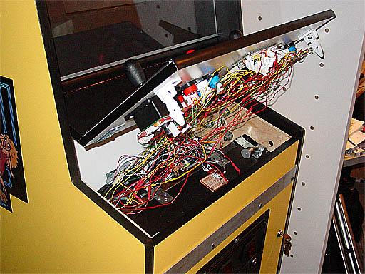
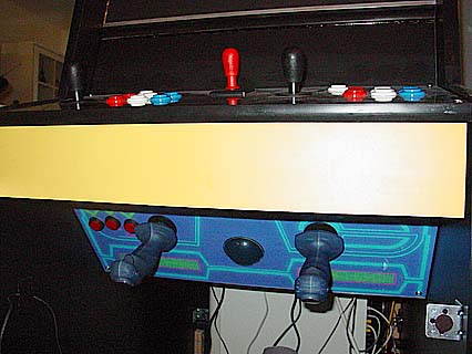
And there's the whole thing together, with the CP
attached by a piano hinge. (Ugh, what rat's nest of a wiring job! I promise I'll clean it
up someday...) Note the white child latches toward the front of the panel. The
black "splash" panel above the white CP provides clearance for the joysticks to
rotate under the monitor. I can put anything up to a full Tron joystick on the CP
without anything scraping. It also provides space to put instructions if I find that
my guests need it. The CP is connected to the splash, which is hinged to the
rotating CP frame with a piano hinge. The plastic child latches click into the holes
on the CP end caps, so I can hinge the CP up for some quick tinkering with the controls.
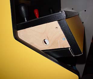
And here, you can see how the panel
latches can be exposed by rotating the panel partially, and pressing the
fingers into the holes to release them for maintenance. Hiding the
latches this way is not only an aesthetic choice, but is also a security
feature. When the front access door is locked, the panels can not
rotate, and the panel latches are inaccessible to guests or children.
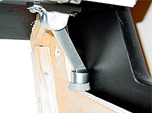
I recently rigged a CP
"kickstand" out of a folding metal door stop. This allows me
to work on the wiring, hands-free! A feature I use often--with all the
daisy-chained inputs and the tangle of wiring, there's always a bad crimp
that needs fixing!
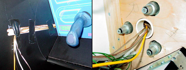
Here's a closer look at the way
that the wiring is routed. All wiring goes out thru a slot that I've
cut in the PVC piping that serves as the hub of the rotating system.
This runs down a 1" wide slot, towards the back of the cabinet, where
the wiring drops down to the PC. Umm...the duct tape is only
temporary, and will eventually be replaced by some plastic or metal clips to
hold everything clear, once I've connected everything permanently.
Here you can see two control panels at
once. One panel comes out, while the previous panel is automatically
tucked neatly away. No muss, no fuss. So simple, even a wife can do it! 
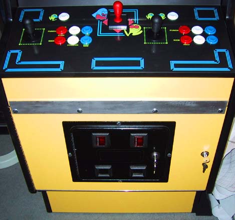
To finish it off, I bolted a metal plate across the
top front edge of the front access door. (Looks ugly in the photo, but
in person it's a nice brushed aluminum texture.) Without it, the door keeps the CP from
rotating downwards during play, but there is a little bit of slack in the roller locking
system, so the CP would wiggle upward a bit during rough play. With the addition of
the metal plate, the CP is also kept from rotating upward when the front door is
closed. So the roller latches allow the CP to automatically click loosely into
place, but the front door provides a second, more stable method of locking everything
down. It also allows me to control access to the rotary feature of my cab, by simply
removing the key! This is good for parties, since my guests don't know how to work
the rotation, and tend to play only on the main CP anyway...
Future Plans
At this point, my cabinet is playable, but I am
planning to make a couple of removable controls for the third, modular panel. These
will be the dual Terminator 2 guns, and the Star Wars yoke. In order to make them
removable, I need to build bases for them from the remaining wood I have. These
bases will have long bolts with plastic knobs fixed to the heads, which can be
hand-tightened down into tee-nuts in the panel. These will go into the PROJECTS section when I have time to finish them.
DESIGN = CONSTRUCTION = ARTWORK
= HARDWARE
= SOFTWARE
= DOWNLOADS |