LIGHTING LIGHTING
Lighting was a key consideration while
constructing Pac-Mamea. Obviously, I wanted to light the coin slots and the marquee,
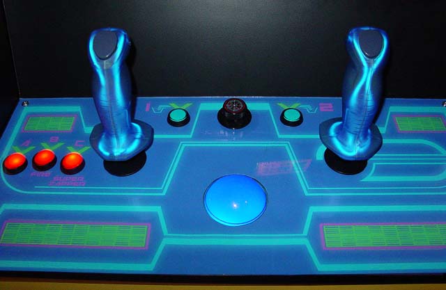
but why not light the control panel as well? For the Tron control panel, I decided
to use Happ illuminated pushbuttons. The incandescent lights that Happ
supplied were replaced with lower-voltage red (1000mcd) and blue (2600mcd)
LEDs, to extend the life of the lights.
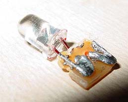 
This was done by
soldering the LEDs onto a small piece of circuit board, approximately the
same size as the "wedge" base on the incandescents. These
custom LEDs were then easily plugged into the illuminated pushbutton
bases.
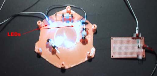
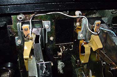
I also wired two 2600mcd
blue LEDs to the base of
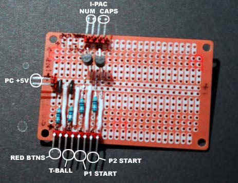
the translucent blue trackball. All the LEDs connect to my custom lighting board,
which draws power from the PC's +5v supply. There are also connections on the board
for the I-PAC's numlock and capslock LED harness plugs, so the P1 and P2 start button LEDs
can be controlled by MAME! Note the transistors for switching the 5V supply to the
start button LEDs.
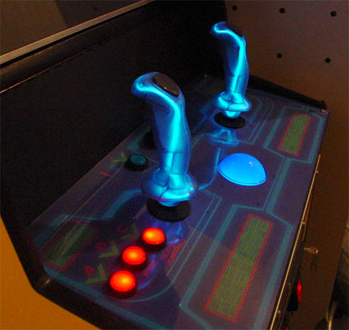
The two translucent trigger sticks are hacked Happ
supers with Raider Pro joystick handles, internally lit with glowire that I got from the
automotive section at Target. The driver box that came with the glowire takes a 12v power
source, but won't run off the PC +12v line. So I had to get a 12v power inverter
from Radio Shack, which has a cigarette lighter plug, so the driver plugs right into it.
Probably would've been cheaper and easier to get a PC mod kit from www.glowire.com and then it would also
power on with the PC!
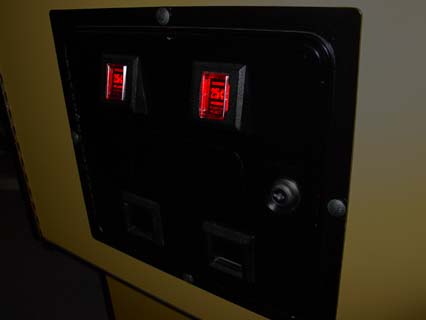
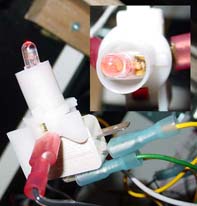
When I received my coin door, it had
no lights installed. Since I had so many LEDs around (left over from
my plans to illuminate every single pushbutton), I decided to use LEDs to
light the coin return buttons as well. To do this, I first removed
the original lighting brackets.
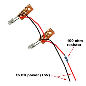
Next, I wired two bright (3000mcd) red
LEDs together in parallel, soldering each to a short piece of PCB with
mounting holes drilled in the ends. A 100 ohm resistor was soldered
to the positive lead, to protect the LEDs from the separate 3v power
supply.
 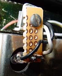
The leds were connected to the coin
door via the original mounting holes and screws supplied for the light
brackets. This puts the LED in a proper position to light the
interior of the coin return button.
DESIGN = CONSTRUCTION = ARTWORK
= HARDWARE
= SOFTWARE
= DOWNLOADS |
| The
information on this site is for the purposes of education and
entertainment only. The owner of this site makes no warantees as to
the accuracy of the information, and takes no responsibility for any
damage or injury sustained due to the use of information herein. The
design of the Pac-Mamea cabinet and all photos, computer renderings,
drawings, schematics, and printed information relating to such are
Copyright © 2002-2004 Robert Meyers. No ownership of other
copyrighted material found on this site is implied. |