|
Construction Notes
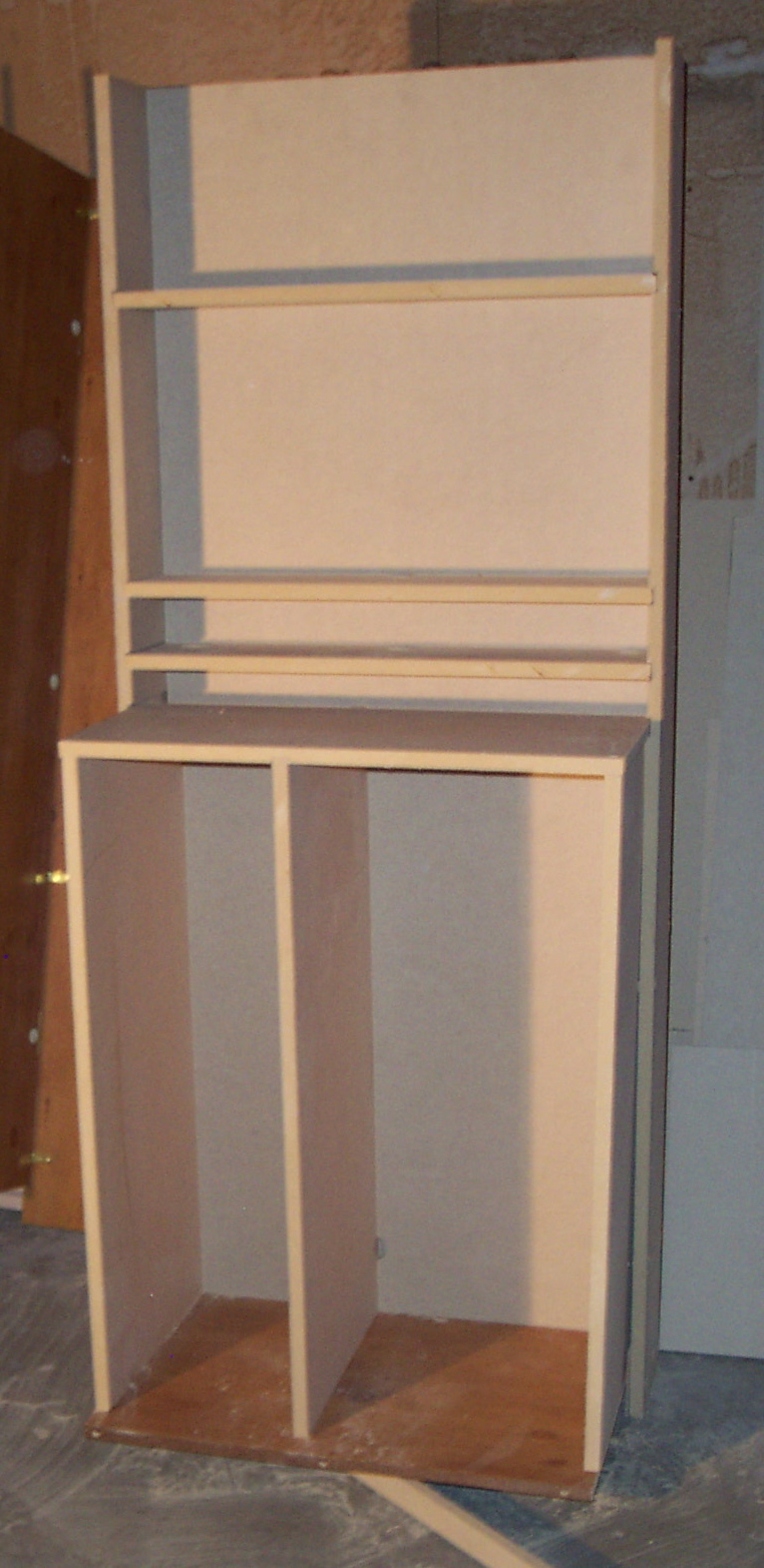
The Inner Cabinet
 Making the inner cabinet was relatively straightforward. I made the whole cabinet out of 3/4" MDF, which was probably overkill and made the cabinet VERY heavy. Making the inner cabinet was relatively straightforward. I made the whole cabinet out of 3/4" MDF, which was probably overkill and made the cabinet VERY heavy.
The cabinet consists of two parts. First, there's a backplane, with a solid sheet of MDF 28" wide by 71 1/2" high. Two sides are attached, 71 1/2" high by 6 3/4" deep. This gives room for the 6" shelves, which fit in dado cuts put in the sides before assembly. Finally, the base pane from the original O'Sullivan cabinet is cut to fit inside the backplane and attached
The lower cabinet extends another 12" The top and sides are 15" deep, so they fit partially inside the backplane. The top does not extend all the way back, so that wires can go below the top. This lower cabinet is 36" high.
The lower cabinet has a vertical divider, dividing the space with 1/3 on the left and 2/3 on the right. Shelves are built for this area, attached to drawer mechanisms so that units can be pulled out for wiring.
Fit and finish were important. Every screw hole was countersinked, and filled before painting. Half-round molding was added to the edges, this covered the dado cuts and gave a nicer look.
After painting, the kick panel from the original cabinet is attached to the front of the base pane. This is the only part of the inner cabinet that is seen while the doors are closed.
|
Rotating Panels
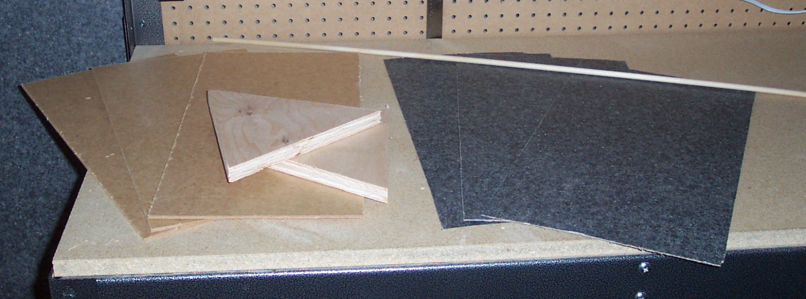
 One of the key features of the secret arcade is the box of rotating panels. It is covered with Formica, and has various features attached. One of the key features of the secret arcade is the box of rotating panels. It is covered with Formica, and has various features attached.
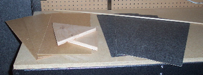
You start by making the five sides, two trianglular sides made of 3/4" MDF with 10" on a side, and three faces made of thin stock (1/4" plywood or pressed board) cut to 10"x24". Drill holes in the center of the two triangles, 1 1/2" wide. This will be used for centering and passing wires later.
|
|
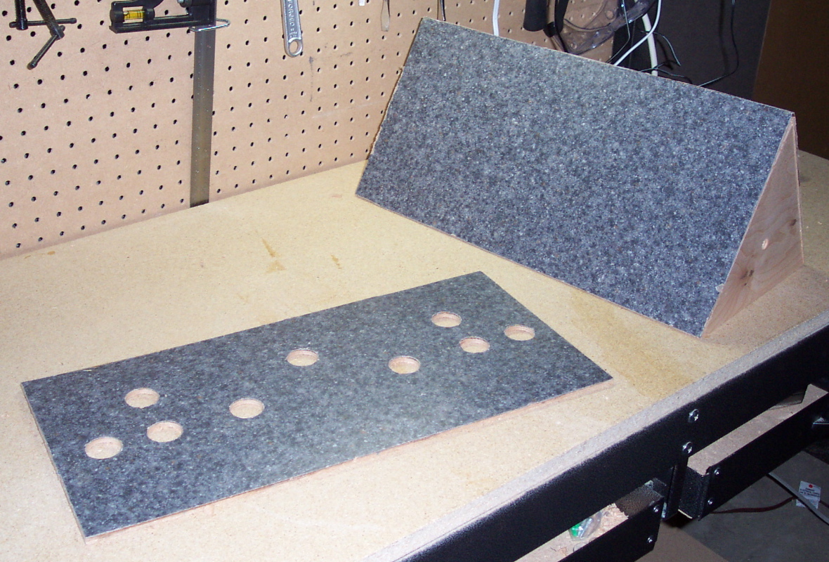
 Attach two of the three faces to the triangle sides. Use screws, being sure to countersink the holes so that the screw heads do not stick up. The third face is not attached at this point, so that it can be opened later. Attach two of the three faces to the triangle sides. Use screws, being sure to countersink the holes so that the screw heads do not stick up. The third face is not attached at this point, so that it can be opened later.
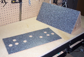
It's now time to add Formica to all sides (including the side not yet connected). This will cover the holes on the sides, so redrill the holes when the Formica is dry.
|
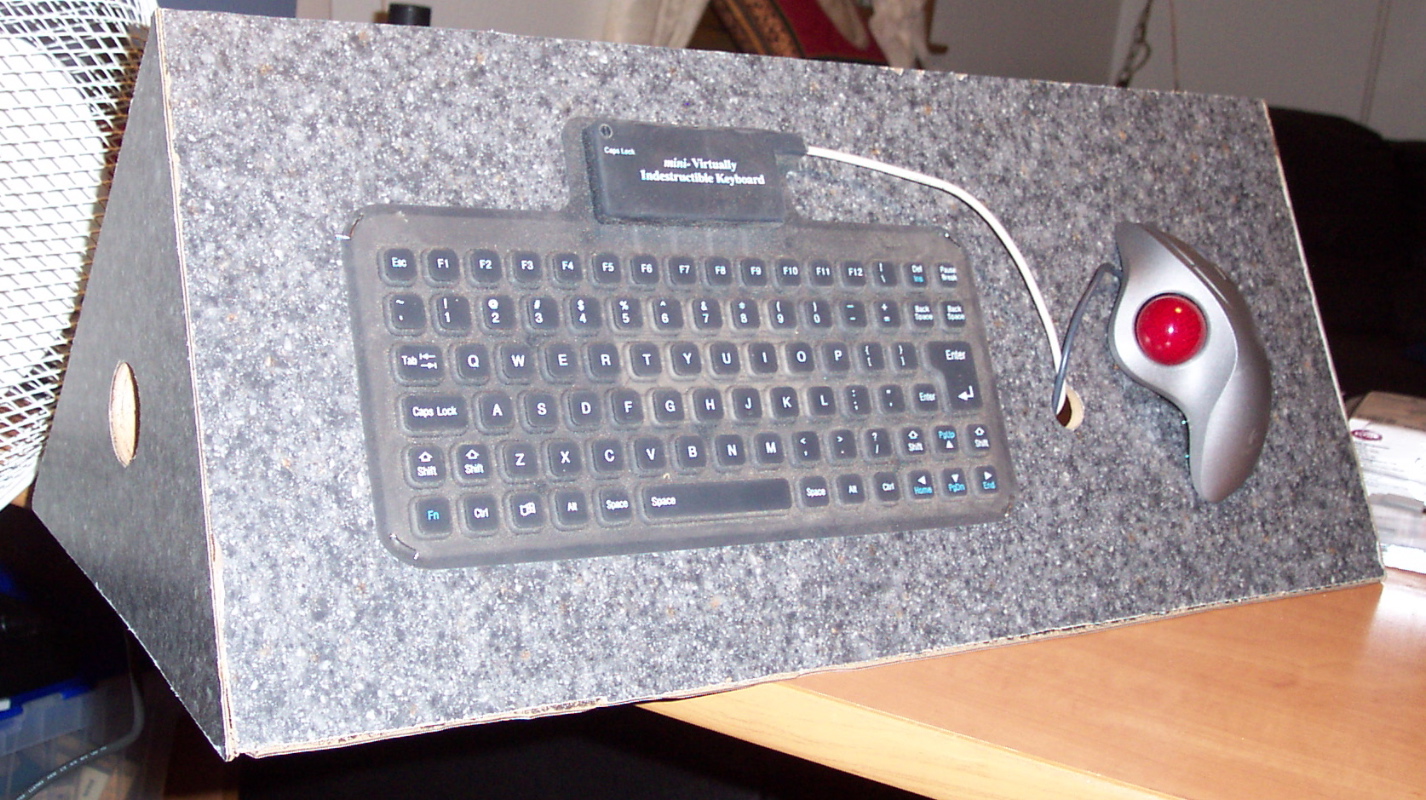
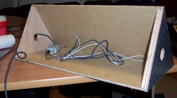 A USB hub is attached to the box by epoxy. A long cable is connected and passed out one of the side holes. A USB hub is attached to the box by epoxy. A long cable is connected and passed out one of the side holes. |
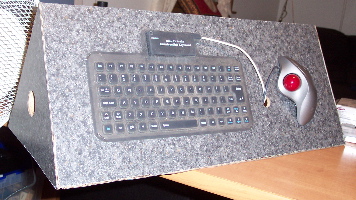 The keyboard and trackball are attached to one of the panels attached on the box. A hole is drilled, the cables from the keyboard and trackball are threaded through the hole and then plugged into the USB hub. The keyboard and trackball are attached to one of the panels attached on the box. A hole is drilled, the cables from the keyboard and trackball are threaded through the hole and then plugged into the USB hub. |
|
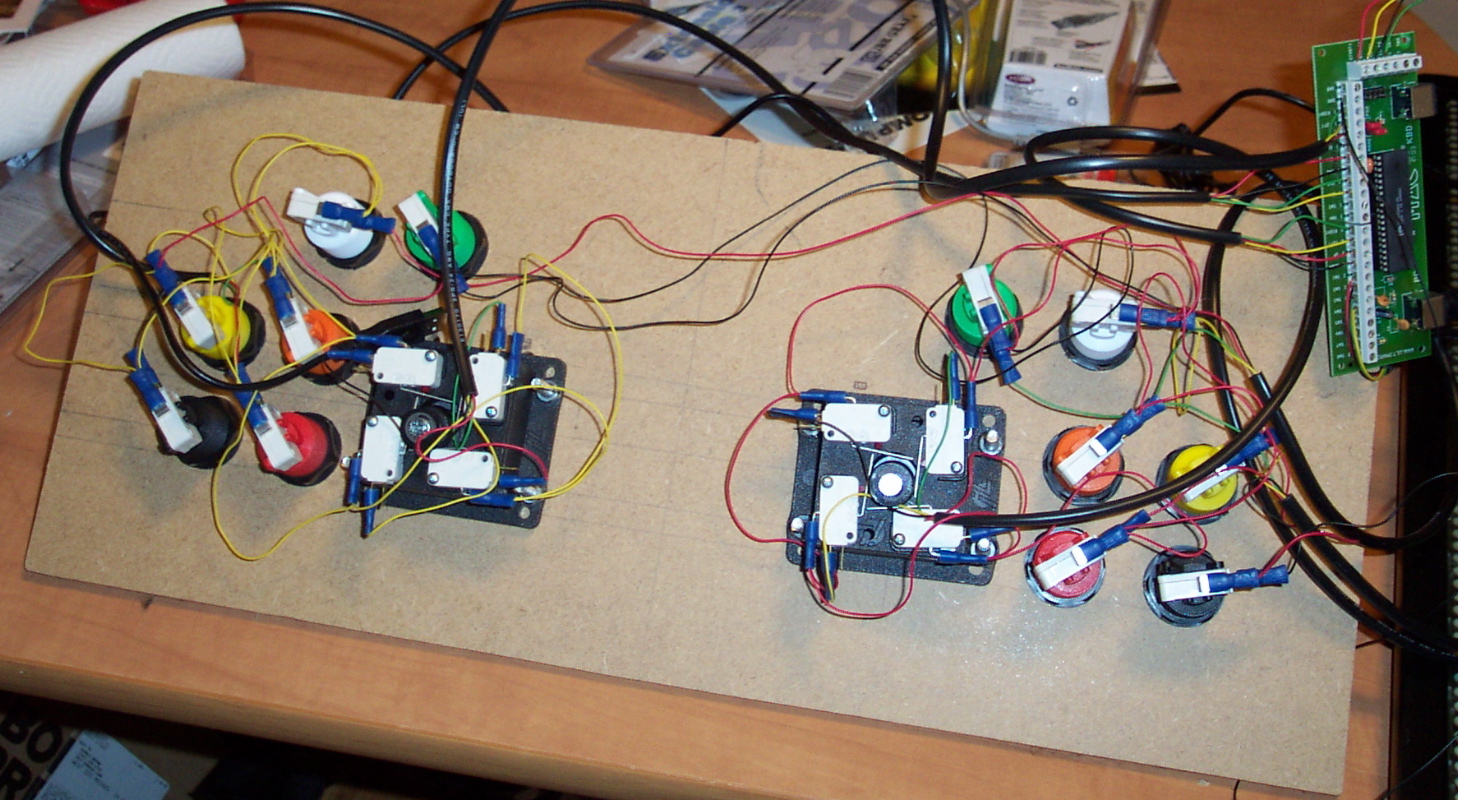
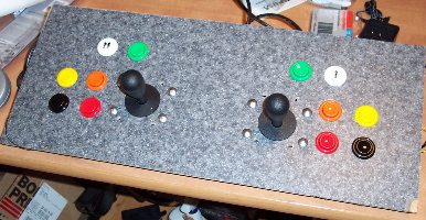 It's now time to drill holes for the joystick and arcade buttons. The joystick should be three inches from a button (six inches between the joysticks), buttons should be at least two inches apart. It's now time to drill holes for the joystick and arcade buttons. The joystick should be three inches from a button (six inches between the joysticks), buttons should be at least two inches apart.
|
|
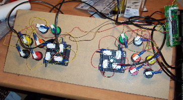 Flip it over and attach the wires. We use a crimping tool to attach push-on connectors to wires, so that no soldering is needed. Each switch has two connectors. One is connected with a separate wire to the appropriate spot on the I-PAC adapter, which converts switch closings to keypresses. The other is connected to ground. We then connect the I-PAC to the USB hub. Flip it over and attach the wires. We use a crimping tool to attach push-on connectors to wires, so that no soldering is needed. Each switch has two connectors. One is connected with a separate wire to the appropriate spot on the I-PAC adapter, which converts switch closings to keypresses. The other is connected to ground. We then connect the I-PAC to the USB hub.
|
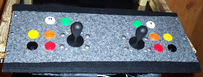 The panel is then connected to the box, and so all sides are now in place. I used black felt to cover the spots where two panels meet. Covers a number of minor sins of misalignment. The panel is then connected to the box, and so all sides are now in place. I used black felt to cover the spots where two panels meet. Covers a number of minor sins of misalignment. |
The Arms
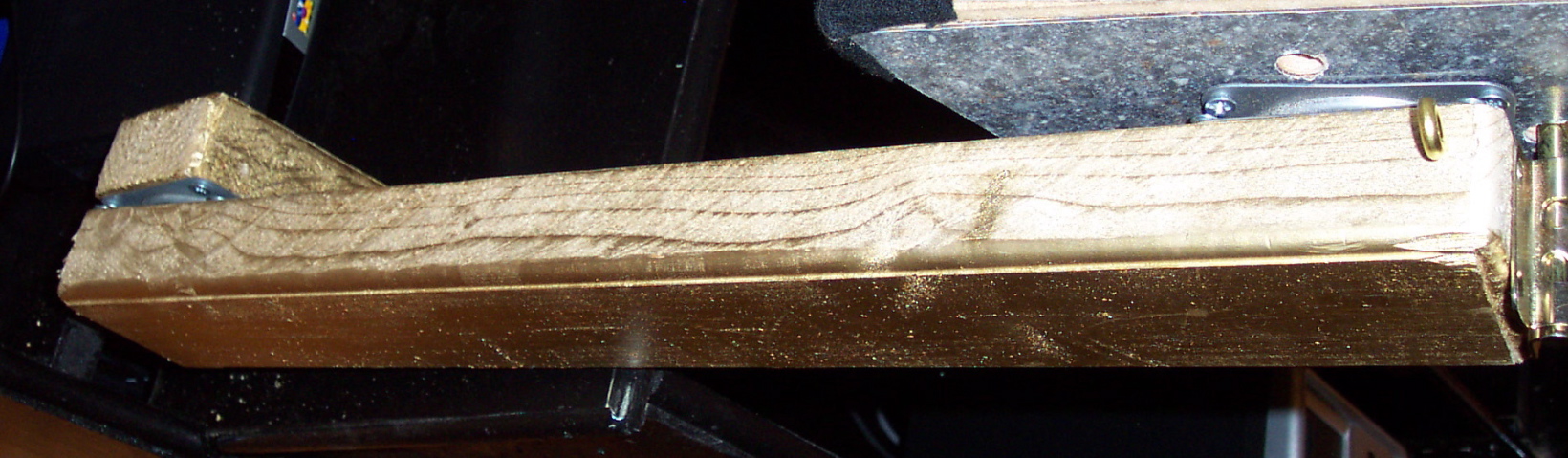
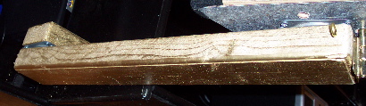 The arms that hold the box of rotating panels is made from 2x4 stock, trimmed to three inches wide, routed, and painted gold. One side has a slot routed down its center to take the USB cable from the box to the cabinet. The arms that hold the box of rotating panels is made from 2x4 stock, trimmed to three inches wide, routed, and painted gold. One side has a slot routed down its center to take the USB cable from the box to the cabinet.
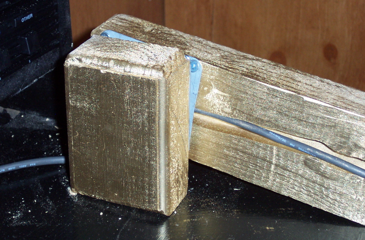
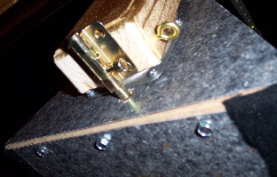
The arms are then connected to the box with 3" lazy-susan hardware. This allows easy rotation, is fairly sturdy, and easy to connect. On the end with the USB cable, be sure to thread the cable through the center of the lazy-susan and down the slot before attaching them.
|
 The other end of the arms are connected to short stubs, made the same way as the arms, again with 3" lazy-susan hardware. The stubs are screwed onto the top of the lower cabinet. The other end of the arms are connected to short stubs, made the same way as the arms, again with 3" lazy-susan hardware. The stubs are screwed onto the top of the lower cabinet.
On the side with the USB cable, the cable is snaked through the lazy-susan hardware and down a hole drilled in the top of the lower cabinet.
|
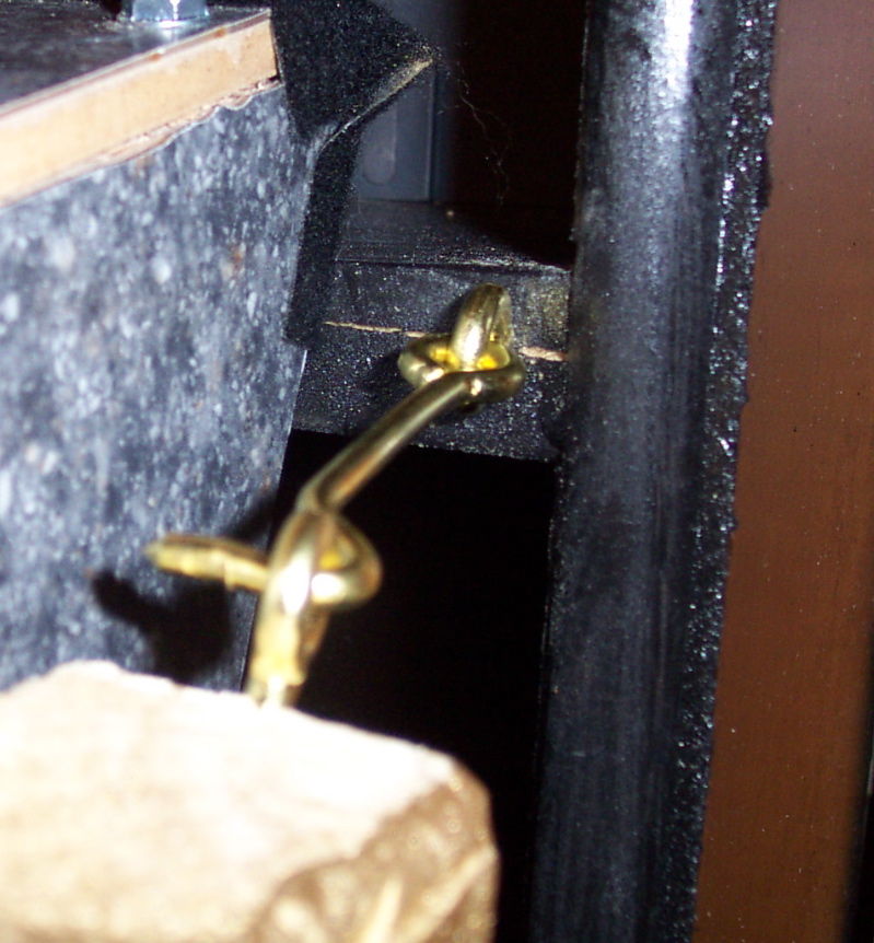
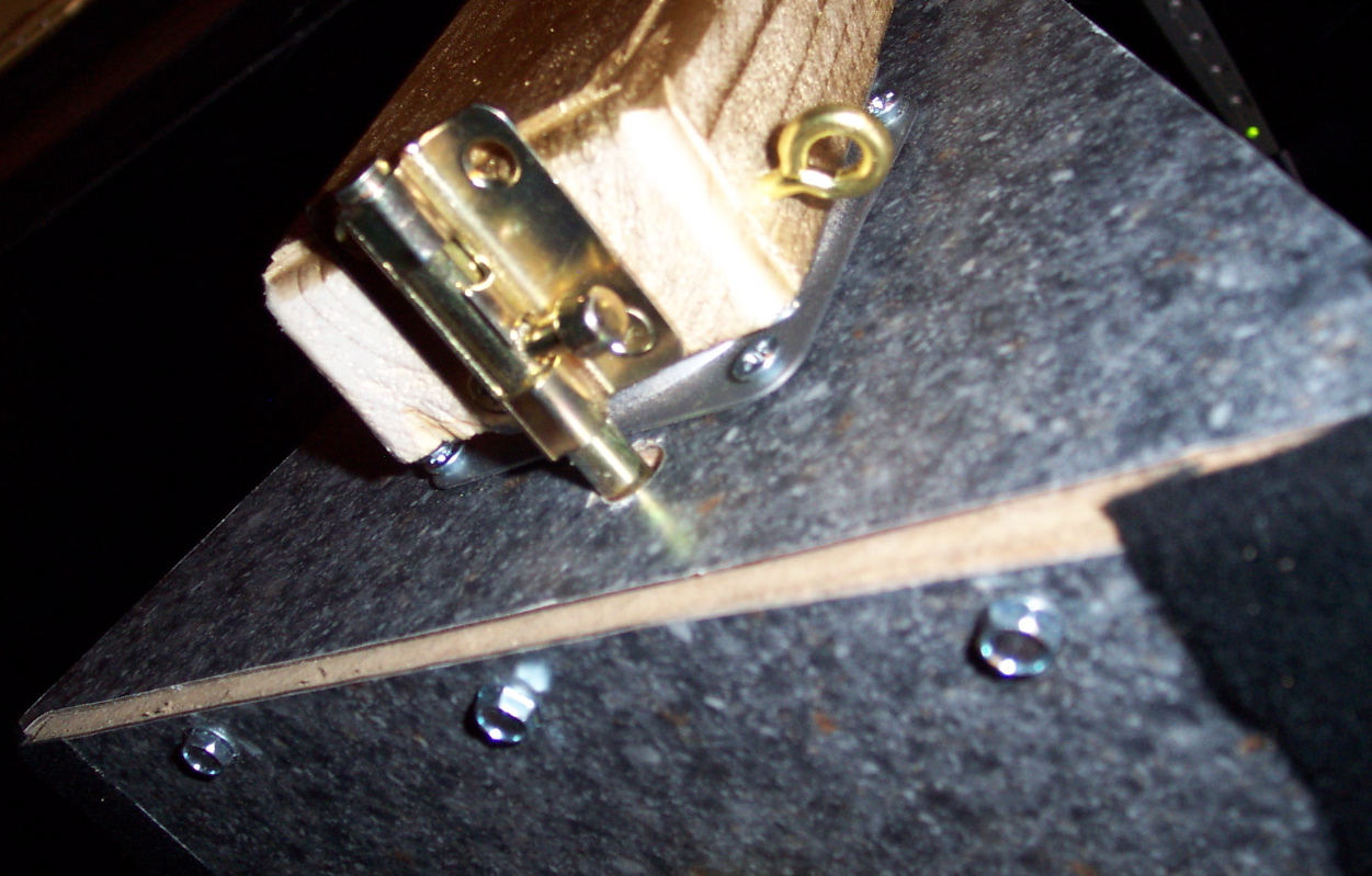
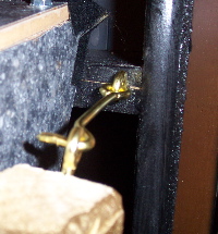 The arms must be able to locked into an upright position. After examining various latches and such, the best solution turned out to be a pair of simple hooks and eyelits. The arms must be able to locked into an upright position. After examining various latches and such, the best solution turned out to be a pair of simple hooks and eyelits. |
 While the box must easily rotate to whichever panel the user wants, it must then be latched into position. This was accomplished by a sliding bolt that slides into holes drilled into the side of the box. While the box must easily rotate to whichever panel the user wants, it must then be latched into position. This was accomplished by a sliding bolt that slides into holes drilled into the side of the box. |
The Doors
 The doors are made from the side panels and the doors from the original O'Sullivan cabinet. Each door is attached to its side with screws drilled from the outside (covered with small stickers included in the cabinet accessories) and with small L-brackets to keep it at a right angle. The doors are made from the side panels and the doors from the original O'Sullivan cabinet. Each door is attached to its side with screws drilled from the outside (covered with small stickers included in the cabinet accessories) and with small L-brackets to keep it at a right angle. |
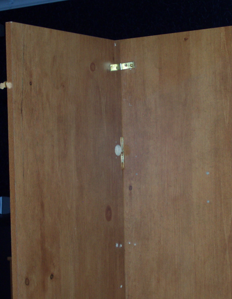
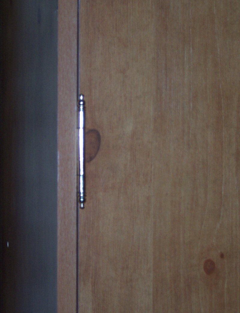
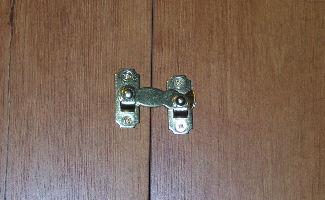
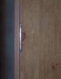 The original cabinet had european hinges, that are invisible from the outside. Since we want to give the illusion of the doors opening from the sides, I added non-functional hinges. The original cabinet had european hinges, that are invisible from the outside. Since we want to give the illusion of the doors opening from the sides, I added non-functional hinges. |
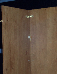
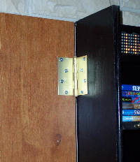 The doors are connected to cabinet by attaching the original cabinet sides to the inner cabinet backplane sides with door hinges. These doors be hung carefully. The original sides must swing freely, and yet not be so high that it's obvious they aren't the sides of the cabinet. Finally, the hinges must not be visible when viewing the closed cabinet from the side. The doors are connected to cabinet by attaching the original cabinet sides to the inner cabinet backplane sides with door hinges. These doors be hung carefully. The original sides must swing freely, and yet not be so high that it's obvious they aren't the sides of the cabinet. Finally, the hinges must not be visible when viewing the closed cabinet from the side. |
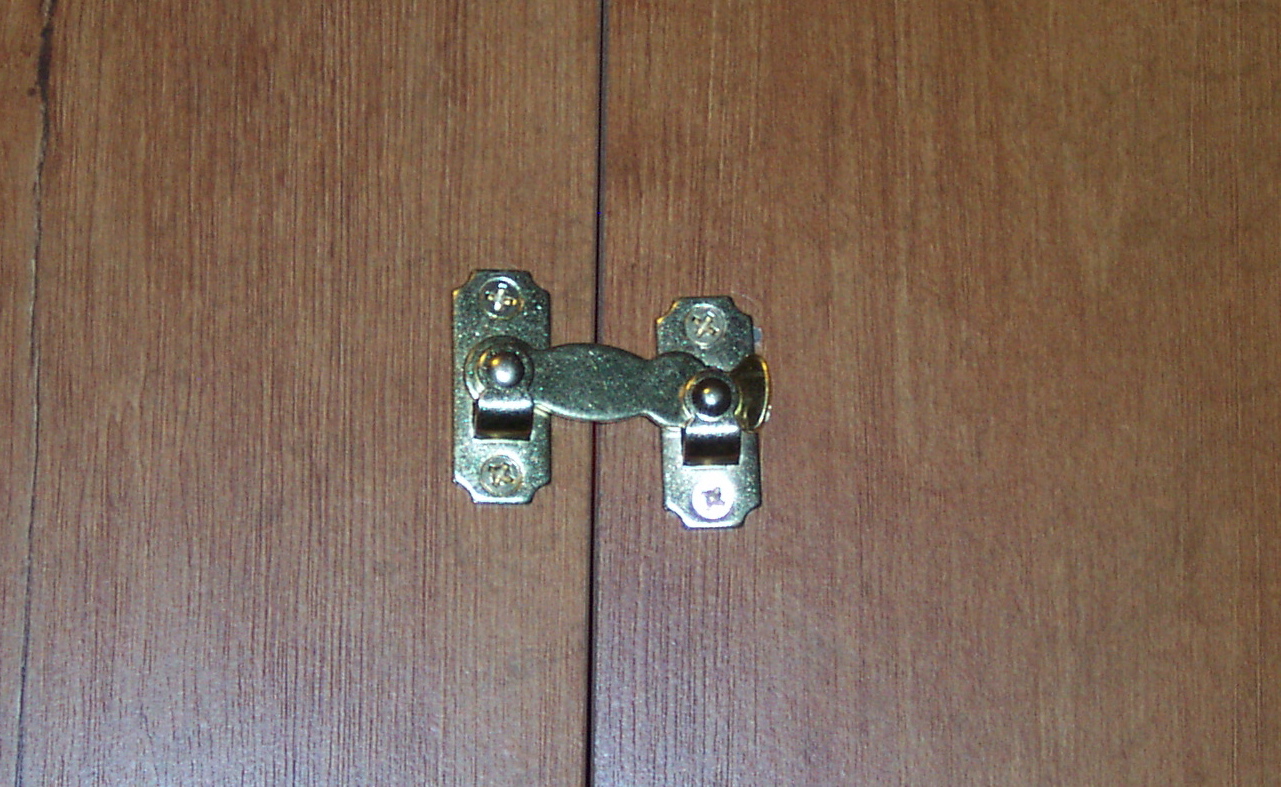
 Ideally, the doors will close neatly together, leaving no crack large enough to see the secrets inside. If not, adding a latch to hold the doors together is not an unreasonable addition. Ideally, the doors will close neatly together, leaving no crack large enough to see the secrets inside. If not, adding a latch to hold the doors together is not an unreasonable addition. |
|
|