|
|
|
|
|
|
|
|
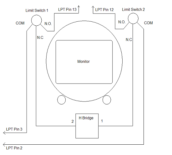
We need a way to determine when the monitor has reached its correct orientation, so we can stop the motor. This is done by mounting two switches in the cabinet. One switch should be pressed when the monitor is perfectly level in the horizontal position, and the other should be pressed when the monitor is perfectly vertical. We are only going to rotate the monitor 90 degrees, clockwise from horizontal to vertical. It’s up to you to determine the best way to physically mount and actuate these switches. The switches should be spdt, and should have a common, a normally open, and a normally closed contact. I used standard Happs pushbuttons with cherry microswitches for my limits, they work perfectly. The limit switches serve two functions: they interrupt the signal from the LPT port to the motor controller when the limit is reached, and they signal the LPT port that the limit has been reached. The wiring is as follows: The output pin from the LPT port (either pin 2 or 3) is wired to common of the limit switch. The normally closed side of the switch is wired to the input of the motor controller. The normally open side of the limit switch is wired to the input on the LPT port (pin 12 for LPT pin 2, pin 13 for LPT pin 3). When the limit switch is NOT pressed, the control signal from the LPT can follow the normally closed path through the limit switch, activating the motor control circuit. When the proper orientation has been reached, the limit switch is pressed and the normally closed circuit is broken, interrupting the signal to the motor controller, stopping rotation. Also, the normally open circuit is now closed, which routes the control signal from the output pin of the LPT port to one of the input pins on the LPT port. Our software will check for this signal and will know when the monitor is finished rotating, and will logically turn off the rotation signal as well..
For the sake of clarity, from this point on, I am going to assume the monitor is normally at rest in the horizontal position, and that when pin 2 of the LPT port is set high, the monitor will rotate to the right, or clockwise, to the vertical position. Limit switch wiring diagram:
The input in the diagram labeled ‘1’ on the H-bridge should be the input which when active, causes the monitor in this configuration to rotate to the right, or clockwise. In the diagram above, with the monitor in the horizontal position, limit switch 1 should be pressed and held as long as the monitor is horizontal. When the monitor is fully rotated to the vertical position, limit switch 2 should be pressed and held as long as the monitor is vertical. Although not shown in the diagram, the power supply for your motor is connected to the power input of the h-bridge, and your motor is connected to the power output of the h-bridge,
|
| [Home] [What you Need] [The Controller] [The LPT Port] [Monitor Power] [Degaussing] [Limit Switches] [Software] [Action!] [Notes] |
