|
|
|
|
|
|
|
|
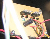
The motor controller is the heart of the project. It takes the low level signals from the PC’s parallel port and uses them to control the higher power required by the motor. There are a few ways this could be accomplished , the most common being relays or a solid state circuit to switch the power. Relays pose a few challenges for this application. For one, the parallel port of the computer typically does not provide enough current to activate the coil of a relay large enough to handle the power we need. Also, when power is removed from the coil of a relay, the collapsing magnetic field can generate a spike that can wipe out our parallel port. The mechanical nature of relays does not really make them suitable to implement any type of speed control as well. For these reasons, I decided to use a circuit called an H-bridge. An H-Bridge is a simple motor control circuit used in all kinds of applications, and is perfect for our needs. It is designed to work with the low level signals like the kind from the parallel port, works fast enough that we can use it for speed control if we want, and does a decent job of isolating the PC from the higher power being switched. It works like this: The leads from your power supply are connected to the power input on the H-Bridge, making sure the polarity matches. The motor is connected to the power output of the H-Bridge, and it doesn’t really matter which way the leads are connected. The bridge has two low level control inputs. If the first input is high, power passes straight through the circuit, and the motor turns one direction. If the second input is set high instead, power flows through the circuit with the polarity reversed, reversing the direction of the motor. The circuit I used can be found here. This circuit can be built for a few dollars and a little patience. If you want to build this, you can wire it on a breadboard, or etch your own PC board using the image file on the site. You can buy breadboards or PC board etching kits at most Radio Shacks. Here is a link to a great site detailing how to etch your own PC board using a laser printer to transfer the PC board image. Here is a parts list for the circuit, including DigiKey part numbers and prices. The component cost for the whole circuit (excluding the board) is less than $6. I think DigiKey charges $5 handling on orders under a certain amount, so if you need more supplies go for it. Picture of the circuit as built and installed in the cabinet:
If you don’t want to build the circuit yourself, there are a few hobby/robotics sites that sell these types of circuits, either prebuilt or as kits. Pololu (another great site) has this one pre-built for $27 (free shipping) that should be perfect. Hobby Engineering has this kit for $17 that can actually control two motors. Less expensive but requires assembly. Before using any of these circuits, use a meter to check how much current your motor draws when it runs. Make sure whatever circuit you use can handle that amount. Also, both of these circuits have ‘enable’ pins, you will need to jumper these high (+5v) to use them..
|
| [Home] [What you Need] [The Controller] [The LPT Port] [Monitor Power] [Degaussing] [Limit Switches] [Software] [Action!] [Notes] |
